
Sam Hallas' Website
[click images for larger view, Back to return]
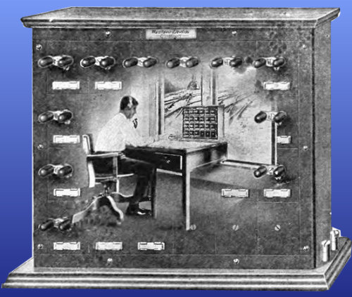
The Standard Telephones and Cables railroad dispatcher's control telephone system was developed under licence from a system introduced by Western Electric in the USA in the early part of the 20th Century. It was featured in their catalogue for 1916 (picture, right).
US Collector and TCI member, Paul Wills, has a set of Western Electric equipment that you can see at his Cedar Knoll Switchroom web page. Compare the WE 60A selector with the STC 4301 selector below and note the similarity.
Mike Tyrrell informs me that the earliest installation he knows in the UK was probably at Doncaster in 1914. The early equipment had a WECo badge, but it appears that shortly afterwards STC began manufacture at their New Southgate works. Many railway companies adopted it for their control networks including LMS, LNER, and GWR. The Southern finally caught up in 1942 with the increased traffic in wartime.
The system was extremely robust and worked well over long distances of open-wire pole routes. As evidenced by the handbook I have been able to scan, it was still being manufactured in 1957, some half-century after its introduction.
As elsewhere I am quoting from Railway Signalling and Communications by Tattersall et al, published by the St Margaret's Technical Press sometime in the 1930's. See the Document Repository page for more extracts.

"To control effectively the movement of trains it is a very general practice to centralise the control at an office or offices and connect all the essential signal boxes, etc., on the route to an omnibus circuit. A special selective circuit is used so that each point can be rung individually, this circuit usually incorporating a rotary switch or "selector" at each station, such switch being stepped by a series of impulses from the control office. A typical circuit is shown in Fig. 172. The rotary selectors, known as type No. 60A, at each station are connected, with a series condenser, across the line wires, being stepped by the condenser charges and discharges, the result of a series of batterv reversals from the control station.

Notice from the circuit diagram that the reversals pass through a high-pass filter formed by the series retard coils and parallel capacitors. This smooths the waveform into a low-frequency alternating current of about 3.5 Hz. What is not shown is the voltage of the main battery used for signalling on the line. The lowest value recommended is 120 volts and the highest shown in the handbook is 460 volts. The energy contained in the pulses may be low, but it would give a lineman a nasty jolt if he were up a telegraph pole and touched the open wires during signalling.
There are pictures of an early control box at the Cedar Knoll switchroom. Theinductors to provide the smoothing are huge. By 1957 magnetic properties had improved and the picture on the left from the STC catalogue shows much smaller inductors.

"The contacts on the selector are so arranged that a local bell circuit is completed when the selector receives the correct combination of impulses, and its own bell, and no others, will be rung, no two combinations being alike. These combinations usually consist of three sets of impulses, the total number of which always amounts to seventeen. Thus station numbers could be 4, 3, 10 or 5, 7, 5, etc. Arrangements can be made for a group of stations to have a common call. Two or three groups can be provided for on one control circuit. In these cases it is usual for all stations of any one group to have the same first digit, and they may all be called together, when the dial system is in use, by dialling that digit only.

"The local bell circuit is completed on step number 17, but the rotary portion of the switch will not reach this step if the first two digits are not appropriate to the station. This is accomplished by the insertion of two pins on the circumference of the selector "wheel", e.g., if the station number is 4, 3, 10, a pin will be inserted to prevent the wheel restoring after the receipt of four impulses, and similarly the second pin will be inserted to prevent the wheel restoring after a further three impulses, and the selector will then step to position 17 on receipt of the last digit of ten impulses.
The picture shows the selector wheel stopped with the pin held after the first impulse train. This selector is set up for code 8-7-2. The second pin can be seen further clockwise round the wheel. The final bell-operating fixed pin is just visible two steps further round still. The function of the other two rivetted pins is not explained in Tattersall, but appears in the full handbook - see below. (SH.)
As other selectors on the control circuit will have, at least, the second pin in a different position, these selectors will restore after the second digit and will not reach position 17. The code of a station can be easily changed by altering the position of the pins. Contacts are arranged on the bell to send a tone to line to indicate to the control officer that the station is being rung.


"The control-office equipment for setting up the codes may consist of a bank of keys, each key having a mechanism to send the appropriate code for each station, or the codes may be "dialled" by using a standard automatic dial, this now being the standard arrangement. Where the dial system is employed, the selectors shown in Fig. 172 may be employed, but the third train of impulses is sent automatically and only two digits are required for dialling. All stations on one control circuit may be called at once by sending a complete train of seventeen impulses.
The selector key case left is a Western Electric model in the collection of Paul Wills, to whom thanks for the photo. It is identical to the one shown in the STC manual (See below). The selector key pictured right can be seen to be a clockwork dial mechanism capable of producing up to 17 pulses with shading cams to provide the inter-digit gaps. It is very similar to the mechanism used by STC on their selective signal post telephone system. [RH Picture: STC/ LH Picture: Paul Wills]
"It may be desired to connect a control circuit of one section to that of another for inter-communication between control offices. This is usually provided by having a selector arranged to complete a local relay switching circuit, upon receipt of a continuous train of sixteen impulses. In some traffic-control systems the three-stage selectors are replaced by rotary switches similar to those used in automatic telephony."
The last sentence may be a reference to the GEC Control Telephone System which follows. This uses special uniselectors as the selective element.

When the selector has been stepped to the correct position on receipt of the correct code sequence, a contact is closed between the selector wheel and the fixed contact below - picture right. A DC bell is operated from the local battery. The bell clapper is arranged to interrupt a circuit causing a tone to be returned to the Controller to confirm that ringing is taking place - see the circuit diagram above. The control equipment pauses for several seconds while the bell rings and then sends a final impulse to release the selector and stop ringing the waystation. Listen to the sound the selector makes as it steps (from the Cedar Knoll Switchroom). You can also see one in Richard Pike's collection in operation on YouTube
By suitable grouping of waystation codes, several stations call be called simultaneously. For example, all stations with an initial digit of 3 may be called by sending two strings of pulses, the first of three and the second of 14 pulses. Alternatively all stations with a final digit of 10 may be called by sending two strings of 7 and 10 respectively.
To call all stations at once it is only necessary to send a string of 17 pulses.
It was standard practice for Controllers to be listening at all times, either on a headset or a loudspeaker. Nevertheless the system was designed to detect a calling loop from any waystation in order to operate a sounder. It was also possible to use magneto generator calling where there was no direct metallic path from the waystation.

The Control Telephone System has an additional feature which allows a time code to be sent to the waystations from a master clock in the Control. The Controller operates a time sending key which advances all selectors to the time receiving postion - the 22nd position of the wheel - picture left. The wheel can be seen here stopped at its 22nd postion. The brass strip fixed by rivets between postions 22 and 24 is now in contact with the retaining lever, preventing the wheel from returning to its home position. All stations are now prepared to receive the time signal. The brass contact strip which previously made the bell circuit can be seen at the back. On receipt of the next impulse this contact is made to sound the bell briefly and the wheel steps back so that a series of short bells can be sent as a time code. Finally, a further series of 3 pulses steps the wheel to step 25 and it is then free to return home. As can be seen (above, right) the regular bell contact and the time contact are connected together to permit this.
Because the STC system uses effectively a low-frequent alternating current for signalling, it is possible to operate over circuits with no metallic path by the use of transformer coupling.


The circuits from two adjacent Control Areas can be coupled togther by the use of a special waystation equipped with two selectors. Pictured right is such a unit to connect two control sections together. The two selectors are operated from each of the two Controllers' desks.
A control circuit can be connected to a battery-calling omnibus circuit with a special interface waystation - Picture left. Omnibus telephones at signalboxes or other sites are fitted with an additional call button which provides a unique calling signal to operate the interface. See the two-button and plastic bodied telephones pictured on my Kidderminster Museum page.
A full handbook for the system can be found in the Document Repository's Railway section
There is a very full and clear explanation of the Western Electric Dispatcher's Control Telephone System at
http://www.telephonetribute.com/railroad_phone_equip.htm
The Bell Telephone Manufacturing Company sold the Western Electric system in France. There is a paper on the subject presented to the International Railway Congress in 1925 describing the system's advantages and method of operating with illustrations of the component parts. In French, courtesy of Remco Enthoven [1.85 MB]
Control of Railway Traffic Operation by Telephone and Teleprinter: A report for Indian Railways describing some of the problems and design considerations for the system as used on the sub-continent. Courtesy of John Goldfinch. [189 kB]
Railway Train Dispatching Telephone Systems Western Electric Instruction Bulletin No 672 - complete set of instructions for the selector system, 117 pages, 26.9MB. Courtesy of Steve Cichorsky at Telephone Collectors International.
Railroad Telephone and Selective Apparatus Western Electric sales information and description, 55 pages, 20MB. Courtesy of Steve Cichorsky at Telephone Collectors International.
Railway Dispatching and Communication Equipment Western Electric comprehensive sales catalogue T 2468, 175 pages, 20MB. Courtesy of Steve Hilsz at Telephone Collectors International.
Next: GEC Control Telephone System
References: Railway Signalling & Communications, Tattersall et al,
The St Margaret's Technical Press, unknown date.
Western Electric Catalogue and Yearbook, 1916.
Traffic Control Telephone Systems, Circuit Descriptions and Hints on Maintenance, Standard Telephones and Cables, 1957.
Acknowledgements: Many thanks to Paul Wills and Steph Kerman in the USA, John Mulrane in Ireland, Remco Enthoven in the Netherlands and Mike Tyrrell, John Goldfinch and Richard Pike in the UK for their help in compiling the information on this page and especially to Richard Pike for letting me photograph the items in his collection.
Unless otherwise acknowledged, pictures © 2008 Sam Hallas. Non-quoted text © 2008 Sam Hallas