
Sam Hallas' Website
STC's rivals, the General Electric Company, were keen to enter what they perceived as a lucrative market for control systems, for the railways and utilities such as power companies and oil pipelines. Without access to the Western Electric patents, GEC were obliged to develop their own system to satisfy this market.
Most of the images can be clicked to open a larger version. Use your 'back' button to return
The Western Electric system used current reversals to signal to line, which overcomes problems caused by the high resistance and capacitance of the line. It is a principle that has been in use since the earliest long-distance telegraph circuits and does not form part of the WeCo patent. By using polarised relays, similar to telegraph relays, to detect the current reversals, GEC was able to produce a suitable method of signalling to the waystations.
Simplified schematic of GEC Control System [redrawn SMH]
The simplified schematic omits details such as the speech battery and concentrates on the line signalling. The means of producing the current reversals is much the same as for the Western Electric/ STC system. The difference lies in how the waystation selection works.
The GEC system uses fairly standard equipment from automatic telephony. The Control Office uses a telephone dial to send impulses to line. People who worked with the system recall that the dial was much slower than a normal telephone. This would help to compensate for the long lines used. The waystation uses a uniselector to receive the selection digits. The early version, as described in the GEC Journal of 1931 used an 11-point uniselector with a release magnet - right. It is rather similar to the digit register used in the Siemens No 16 telephone exchange.
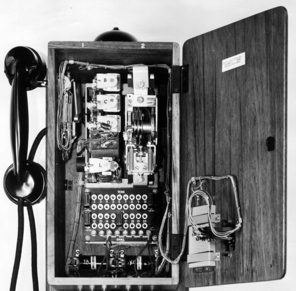
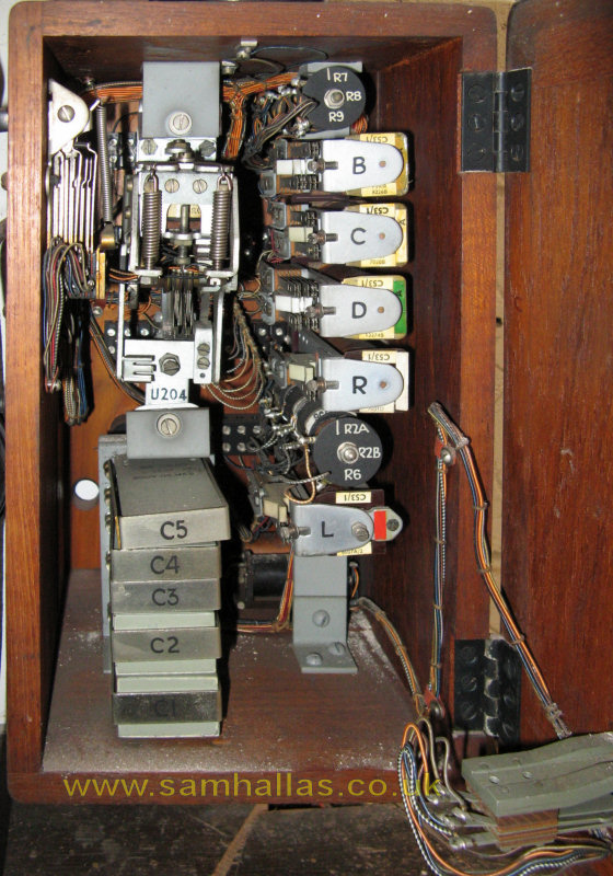
To judge from the pictures in the GEC archive it was not long before the non-standard uniselector was replaced by the Post Office standard uniselector No 2 - see left. It has a single arc of 25 contacts and a homing arc. The polarised line relay is labelled 'L' in the middle on the left. Below is the plug board which selects the waystation's calling code.
By using a two-digit numbering scheme the GEC system allowed for up to 90 telephones on one circuit. A single digit was reserved for an all-call facility.
As the operator at the Control Office dials the first digit, all the uniselectors at waystations step along with the dial pulses. After the first digit is received, a relay operates at waystations with that digit as the first digit of its number - set by the plug in the 'tens' row. At this point the 11-point uniselector is released ready to accept the second digit. Without diagrams it is unclear what occurs to the 25-point uniselector. It is unlikely that there is time between digits for the uniselector to return home, but it might be arranged to move onto step 11. This could explain why the units part of the plug board is labelled 11 to 20.
The second digit received from the Control Office steps the uniselector again. Only one waystation has the correct plug settings allowing the bell to ring. In the same way as on the STC system, a contact on the bell causes a tone to be returned to the Control Office to prove that the bell is ringing. The bell continues to ring until the telephone is answered or the Controller clears the call.
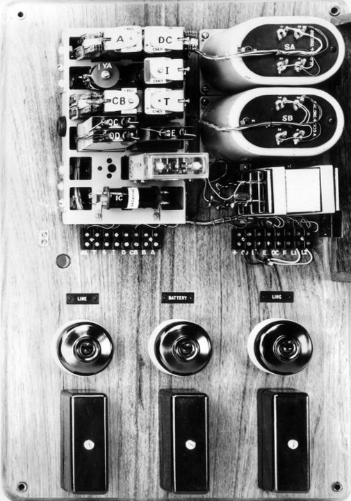
The transmitter unit at the Control Office is pictured on the right. Although there is no mention in the GEC articles, there is evidently filtering of the impulsing to line to reduce the transients using the inductors SA and SB and the various capacitors below them. Just above the induction coil IC, is what appears to be a high speed relay which may be the one operated by the dial springs.
Compared with the WeCo/STC system the GEC systems has these advantages and disadvantages.
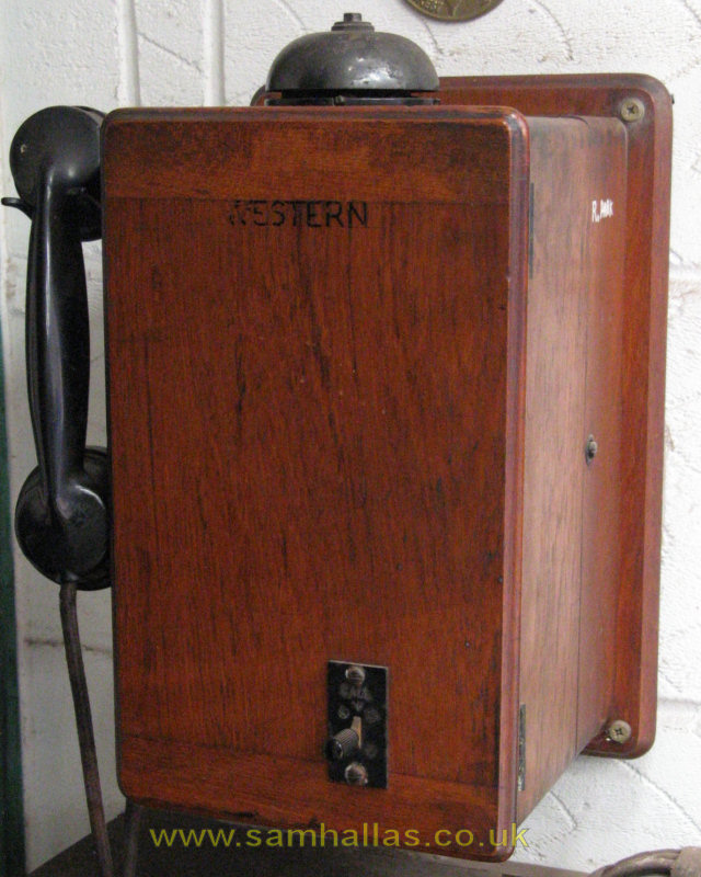
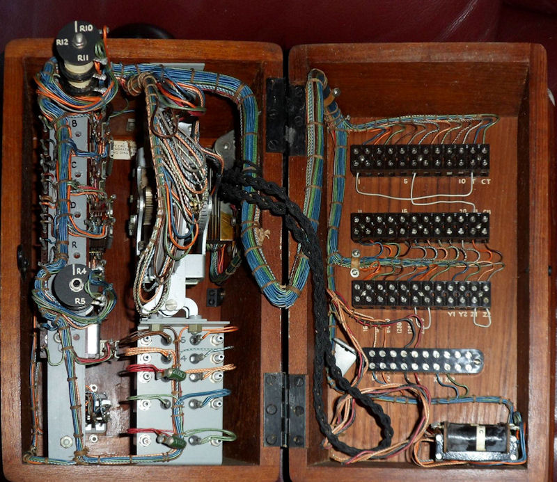
Initially I despaired of finding any preserved GEC Control equipment. Fortunately the Telecom Heritage Group held a swapmeet at the premises of Unicorn Kiosks. I was delighted to discover two telephones from the GEC Control system installed for the British Rail Southern Region Electric Traction Control at Woking. The internal layout differs from the 1930s models in the picture archive. From the lack of plug board I had assumed that the waystation number was hard wired into the uniselector bank. However, THG member, Jack Ryan, pointed me to this web page where it can be seen that the code strapping is done on screw terminals inside the back of the case. I've straightened the perspective in the picture below.
Picture: andysgramophoneclassics
I am not aware of any of the central Control Office equipment in preservation. Please let me know if you know better.
References: Railway Signalling & Communications, Tattersall et al,
The St Margaret's Technical Press, unknown date.
GEC Journal May 1931, Pp 29-34
Control on the Railways, Philip Burtt
Railway Telephones - Article from Newnes part-work ca 1934
Acknowledgements: Many thanks to Mike Tyrrell and Andy Emmerson for supporting information. Also thanks to the staff at Unicorn Kiosks for allowing me to photograph the telephones in their collection. Page updated Sep 2010.
B&W pictures & uniselector diagram © 193x ? GEC. Colour pictures & text © 2008 Sam Hallas.