
Sam Hallas' Website
This is a signal post telephone system produced by Standard Telephones and Cables, based on a design by Western Electric, to allow up to twenty telephones to be connected over a single copper pair to the controlling signalbox. It was designed to fulfil all the safety requirements for railway operational use. [Pictures: STC]
The system employs central battery working of the telephone instruments. A local power supply is used to drive a busy indicator, but loss of this supply does not compromise the safety of the system. There is no hook switch at the waystation telephones: calls are at all times under the control of the signaller. Hence the system cannot fail due to a telephone being left off-hook. There is no provision for calls to be made from the signalbox to the signal post.
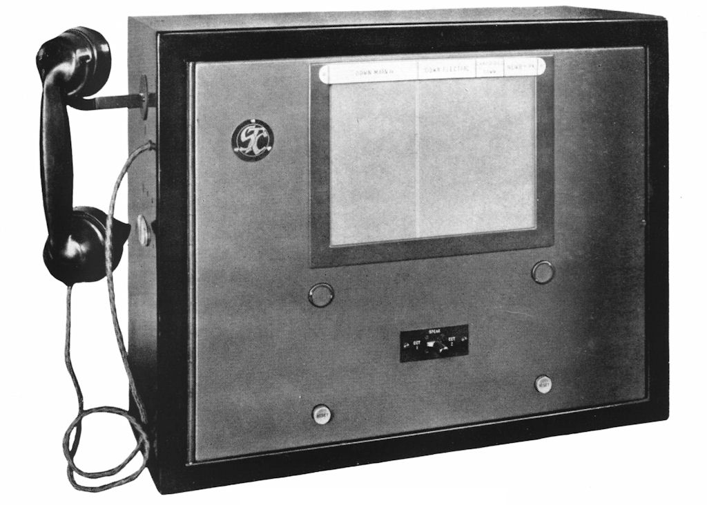
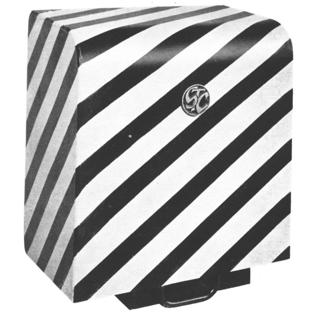
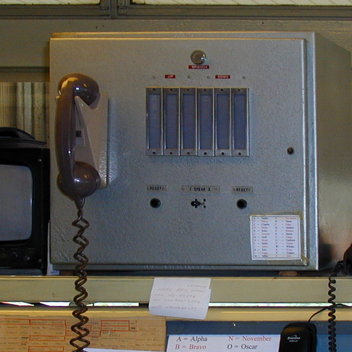
The illustration shows the signalbox display unit (top) and the waystation telephone with the lid closed (bottom)
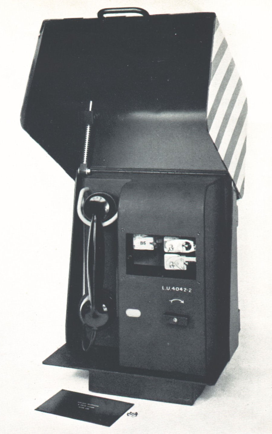
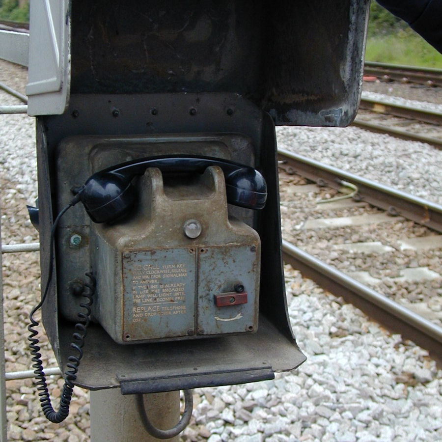
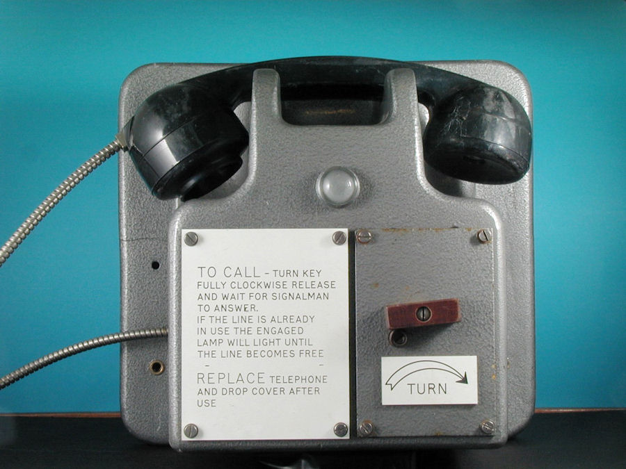
The waystation telephone at the signal post (illustrated with the lid open and inspection plate removed) is constructed of pressed steel. The lid has an up-and-over motion and is damped so that it will not fall shut whilst the telephone is in use.
To initiate a call the handset should be lifted from its cradle and placed against the user's ear. The user then rotates the calling key in the direction shown by the arrow until a stop is reached. The key is then released and allowed to return to its normal position. If the line is free, a call will be signalled to the signaller with an indication of which signal the call is from.
If the line is busy, the busy indicator light will illuminate and remain illuminated until the line becomes free. A fresh call attempt should then be made.
A call is announced to the signaller by a bell or buzzer together with a lamp on the display unit indicating which signal is calling. The signaller answers the call by lifting the handset and speaking to the caller. When the conversation is finished the signaller presses the reset button and replaces the handset. The system is now restored to its idle state ready to accept another call. The busy lamps at any waystation which may have been illuminated are extinguished.[Pictures: STC]
 The requirement for privacy of conversation, such that only one caller can speak
to the signaller at once and no one else can overhear, is met by reversing the
battery polarity on the line once a call has been established. The waystation
telephone contains diodes which sense the line polarity. When the call key is
operated, if the polarity is normal a mechanically latched relay, LT , is operated from
the line current to connect the speech path and impulsing circuitry. However,
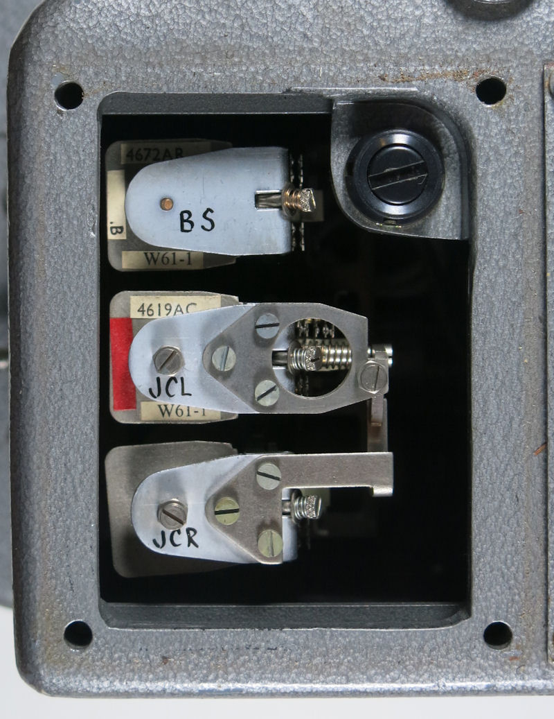
if the line polarity is reversed then a second, high-resistance relay, BS, is
operated which disconnects the speech and impulsing circuitry, lights
the busy lamp and latches itself electrically, until normal polarity is
restored. The latching relay (shown right)is from a later model, hence the different letters. It's actually a composite of two relays mechanically linked. JCL latches itself mechanically and JCR only serves to release the latch: it's contacts are not connected, being provided only to balance the armature.
The requirement for privacy of conversation, such that only one caller can speak
to the signaller at once and no one else can overhear, is met by reversing the
battery polarity on the line once a call has been established. The waystation
telephone contains diodes which sense the line polarity. When the call key is
operated, if the polarity is normal a mechanically latched relay, LT , is operated from
the line current to connect the speech path and impulsing circuitry. However,
if the line polarity is reversed then a second, high-resistance relay, BS, is
operated which disconnects the speech and impulsing circuitry, lights
the busy lamp and latches itself electrically, until normal polarity is
restored. The latching relay (shown right)is from a later model, hence the different letters. It's actually a composite of two relays mechanically linked. JCL latches itself mechanically and JCR only serves to release the latch: it's contacts are not connected, being provided only to balance the armature.
 In order to signal to the controlling signalbox which telephone is calling,
loop impulsing is applied to the line. When the calling key in the waystation
telephone is turned and released it causes a series of break pulses in the
telephone loop current. Two strings of pulses are sent to line separated by
an interdigit pause. The digit strings are received on two uniselectors at
the signalbox display unit. The total number of pulses sent was arranged to
be constant, usually 25 to correspond to a normal 25-point uniselector. The
codes could therefore range from 1 + 24 pulses to 24 + 1 pulses. The indicator
lamps were wired between the banks of the two uniselector as in the diagram.
This system gave a powerful cross-check that none of the impulse trains had
been corrupted, since the total had to equal 25, otherwise none of the lamps
would light.
In order to signal to the controlling signalbox which telephone is calling,
loop impulsing is applied to the line. When the calling key in the waystation
telephone is turned and released it causes a series of break pulses in the
telephone loop current. Two strings of pulses are sent to line separated by
an interdigit pause. The digit strings are received on two uniselectors at
the signalbox display unit. The total number of pulses sent was arranged to
be constant, usually 25 to correspond to a normal 25-point uniselector. The
codes could therefore range from 1 + 24 pulses to 24 + 1 pulses. The indicator
lamps were wired between the banks of the two uniselector as in the diagram.
This system gave a powerful cross-check that none of the impulse trains had
been corrupted, since the total had to equal 25, otherwise none of the lamps
would light.
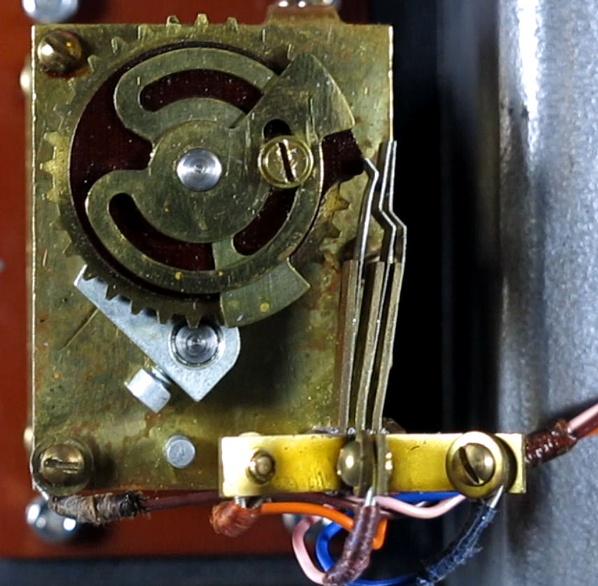 The impulse wheel in the telephone contained sufficient notches
to provide the 25 pulses plus three extra corresponding to the interdigit
pause. A moveable cam plate was fitted to the wheel which blanked off
three of the notches and allowed the code for each individual telephone to
be set. This one is set for code 4 + 21 on a 25-impulse system. Click on the image for a close-up view. You can see the brown fixed cam, made of Paxolin, which is holding the implulse and off-normal contacts closed. The two brass cams can be adjusted by slackening the retaining screw. The width of the brass cam corresponds to the correct inter-digit pause. I'm assuming the second moveable cam is to allow use on 20-impulse systems.
The impulse wheel in the telephone contained sufficient notches
to provide the 25 pulses plus three extra corresponding to the interdigit
pause. A moveable cam plate was fitted to the wheel which blanked off
three of the notches and allowed the code for each individual telephone to
be set. This one is set for code 4 + 21 on a 25-impulse system. Click on the image for a close-up view. You can see the brown fixed cam, made of Paxolin, which is holding the implulse and off-normal contacts closed. The two brass cams can be adjusted by slackening the retaining screw. The width of the brass cam corresponds to the correct inter-digit pause. I'm assuming the second moveable cam is to allow use on 20-impulse systems.
There were systems installed which used a different total number of pulses in the telephone code. For instance, 11 pulses is shown as a variant on the schematic in the handbook. There were others using 16 or 20 pulses.
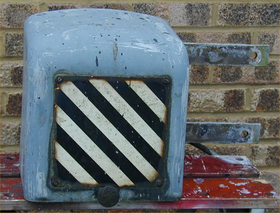 The model on the left had replaced the steel cased telephone shown in the handbook by the 1960s. The case is made from glass-reinforced plastic and the handset is the more modern No 3. The coiled cord is probably not original. A spiral armoured version would have been expected. This example was at Broxbourne in 2001, shortly before being withdrawn from service. I bought a sample of this type of phone which looked like this (right) in 2002 - rather sorry for itself on the outside. Inside it was in quite good condition. I intended to clean it up and take some more photos, but it hadn't happened by late 2015.
 STC introduced a motorised version of the telephone, probably in the late
60s. This was housed in a diecast aluminium alloy body. A push
button was used for calling which set off a small motor to drive the impulse
wheel. The telephone required a 12 volt AC feed, which was provided from
the signalling mains supply.
STC introduced a motorised version of the telephone, probably in the late
60s. This was housed in a diecast aluminium alloy body. A push
button was used for calling which set off a small motor to drive the impulse
wheel. The telephone required a 12 volt AC feed, which was provided from
the signalling mains supply.
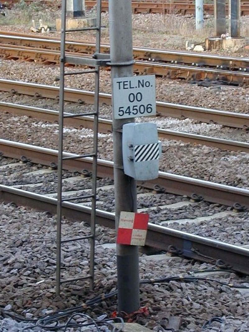
In the early 1970s, STC discontinued manufacture of the telephones, but sold the rights, the designs and diecasting moulds to Clifford & Snell. The telephone illustrated is from this later period. (The telephone number on the sign is the Railway Network number of the signalbox for use on the cab radio system.)
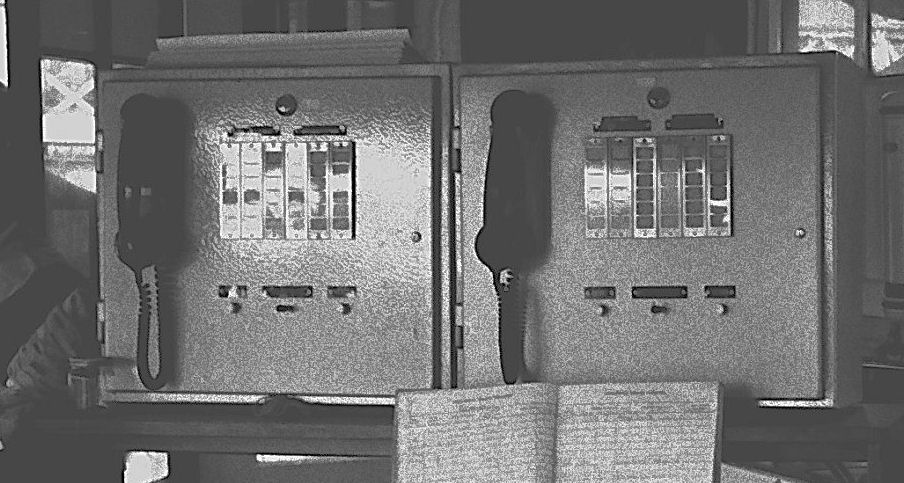
I am unaware of the date when STC stopped making the signalbox display units, or Cabin Units as they were known. Certainly from the 1960s onwards it was common for them to be made in the Railway Signals Workshops, such as York Crewe, and Stratford. Illustrated right are two cabin units made by the Railway Workshops in Wood Green signalbox in the 1970s. Click for larger image. Manufacturers of signalbox concentrators have also made interfaces for STC selective telephone systems, such as Ford Electronics, STS-Intertec,and Kestrel Design.
Still going strong, if a little erratically, I found the unit on the left in service in 2001 at Broxbourne. Just in time, as it turned out, the whole telephone system was due for replacement within weeks. Click for a larger image.
In the 1990s, even Clifford & Snell had stopped making the telephones, due to low demand. Faced with a lack of spares one of the British Rail Regions designed an electronic replacement for the telephone. A small quantity of these were built by DAC (now Gaitronics) of Burton-on-Trent.
I have a copy of the STC Railway Signal Post Telephone System apparatus and maintenance handbook and have prepared a facsimile copy of this in Adobe Acrobat portable document format (PDF). [811 kB] Click here to download it.
Next: Level crossing telephones
Photos & text, © 1977, 2000 - 2002, Sam Hallas