
Sam Hallas' Website
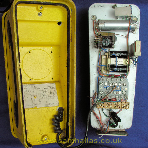
The telephone here is one that had been recovered from service after what appears to have been an arduous life. It was about to be scrapped when I rescued it. [Click images for a larger view and use Back to return]
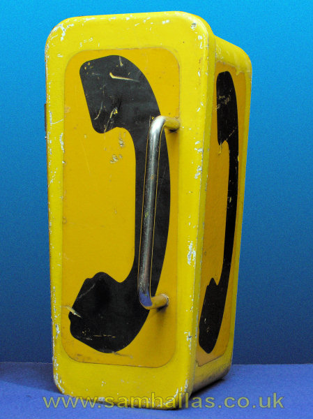
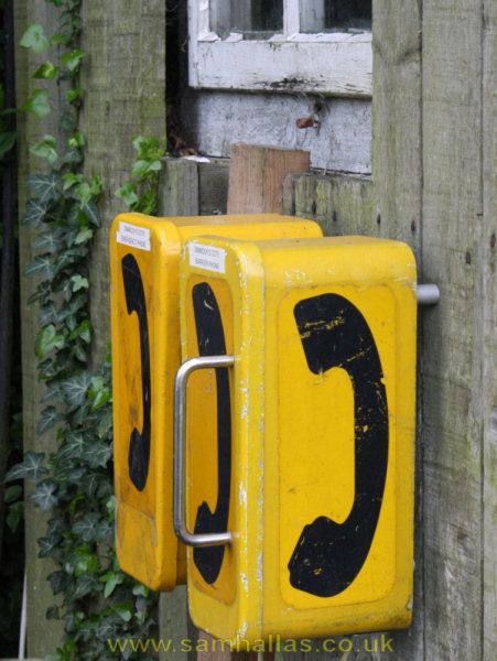
The standard British Post Office weatherproof design has a telephone symbol as a raised moulding on the front face. See Bob Freshwater's page on the Tele 745 for pictures. The level crossing model has a smooth face to allow a self-adhesive label to be fixed. This one must be quite old as the label is not reflective like the one seen in service on the previous page.
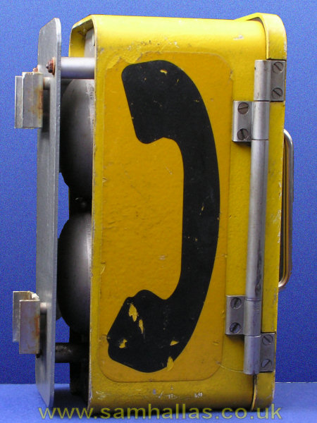
The handle is also a modification for crossing use, occupying most of the height of the door. It appears to be a standard chrome drawer handle. The hinge is again different from the standard phone. The central section contains a torsion spring to ensure that the lid closes automatically. For this reason there is no catch on the lid as on the BPO model.
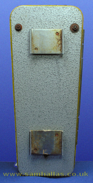
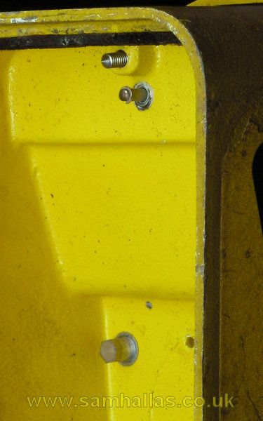
The basic phone would normally be mounted on a wall or back board using long wood screws through the pillars protruding from the back plate seen in the right hand picture above. Here a post mounting plate is fixed similarly with long 2BA machine screws. The plate has tapped holes, so I'm not quite sure why locking nuts have been added to the one pictured here. The post mounting was not peculiar to railway use and was available for the BPO model in various sizes for different diameter poles or posts.
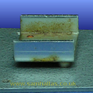
The two U-shaped clamp brackets (one pictured right) allow stainless steel bands to be fastened around the pole and through the clamps to secure the phone to a post.
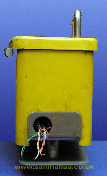
The cable entry is on the bottom where a compression gland would be fitted to secure the cable. As you can see the gland has been removed after the cable was cut. A typical cable would be 0.9mm conductors with brass tape armouring for rodent protection. Seven wires are needed: a speech pair, a bell pair and three wires earth, call button, vandal alarm.
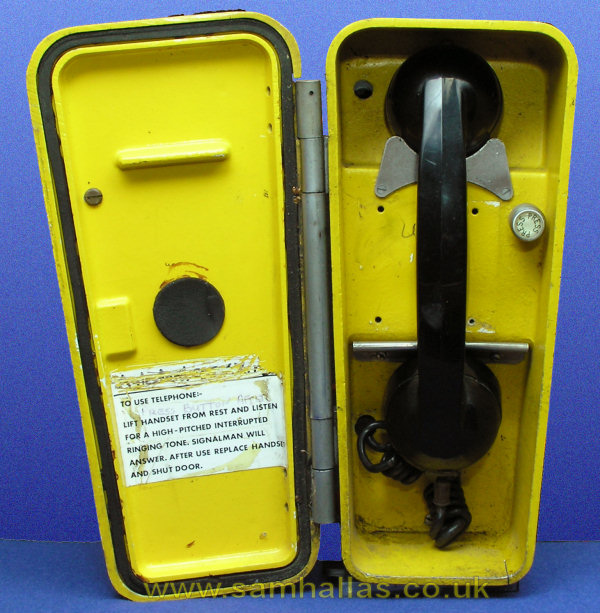
Once the door is open the denuded state of the phone can be seen (right). The Plessey name badge is missing in the top left of the cover. The Beta-Light™ has been removed leaving the fixing holes visible. Click here for a view of a crossing phone in complete condition [Back to return].
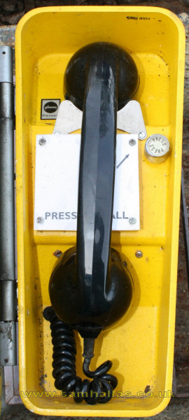
Notice that the inside of the door differs from the BPO version in having a moulded ridge to hold the handset firmly in place when the door is shut. An extra modification has been added with the rubber pad inthe door centre which also serves to restrain the handset. The handset is retained in the stainless cradle at the receiver end and at the transmitter end by the folded spring stainless sheet.
The user instructions do not look like the ones for a post-Hixon level crossing installation and the words 'Press button after..' havebeen written in pen above the instructions to lift the handset. The reason will become clear once the lid is removed.
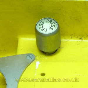
The call button (left) is still the original type used on level crossings. Amazingly it is still luminous after all these years.
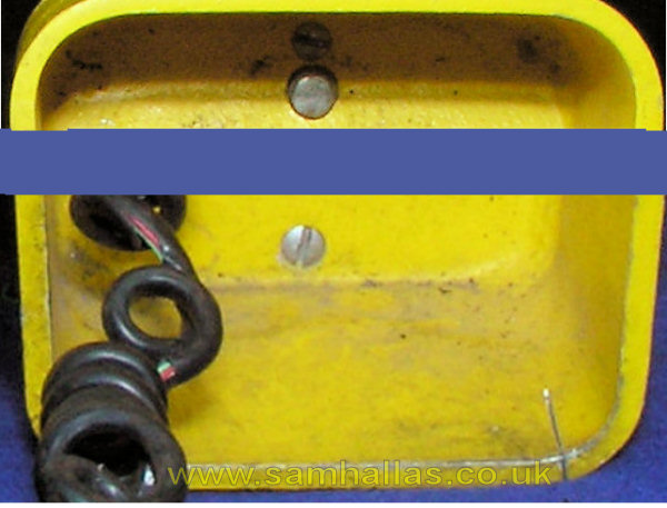
The cover is held onto the base plate by two captive screws at the very top and bottom. The cradle rest plunger is visible just below the top screw.
Once the screws are released the cover can be lifted off. The cover has a gasket around the edge where it mates with the base plate. It has mostly perished in this phone.
Inside the cover the paster diagram is 207568/SW for the barrier telephone. The transmission circuit is the same as for the telephone No 746, but as can be seen, the circuit is hard-wired with no printed circuit board.
From top to bottom the components are:
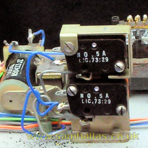
Here's a close up of the call switch (left). The actuating lever is folded so that it operates both microswitches at the same time. The parallel wiring can also be seen. The duplication is presumably a safety feature in case of failure of one switch. The black specks are bits of powdered grommet.
The button actuator shafts can be seen on the right. The call button (lower) is retained by a nut, whereas the hook switch one (top) has a circlip and is much smaller diameter. The handbook warns that the hook switch actuator can be become bent if the cover is fitted roughly. Easy to see why.
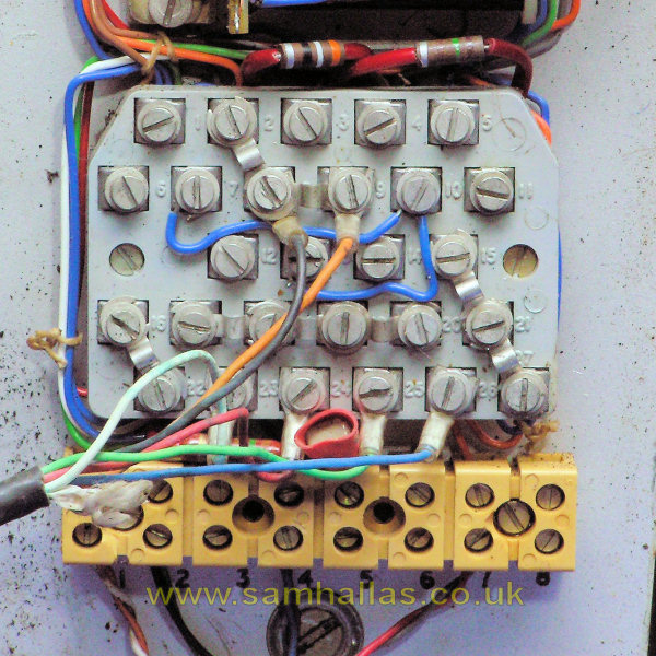
The main terminal block (above) is used to interconnect the circuit components and provide a strapping point for options: the external terminal block (below) is used to terminate incoming cables.
The two resistors at the top of the block are R1 and R2 which are part of the main transmission circuit. The 150 ohm resistor below the block is the one marked 'Note 1' on the diagram to replace the regulator. I can't recall ever seeing a weatherproof phone with a regulator, but maybe some were fitted somewhere. The top of the rectifier element to suppress acoustic noise can be seen between terminals 24 and 25.
The loop which passes up the handset cord to detect vandalism uses the extra black and orange wires in the cord. This is where things start to differ from the diagram. A strap has been inserted between terminals 8 and 9 shorting out the loop. The blue wire connects terminals 7, 10 and 13, and there is a strap between 19 and 20 making the bell no longer a separate circuit but working like a normal telephone. This also changes the call switch to work like a shared service telephone with earth calling.
The external cable was evidently an 8-pair with the spare wires tucked behind the terminal block - picture under 'Insides' above - they had fallen out by the time I took this picture. The wiring uses bunched pairs, not satisfactory from a balance point of view. The colours are those of underground cable: orange/white, green/black, blue/brown, red/slate
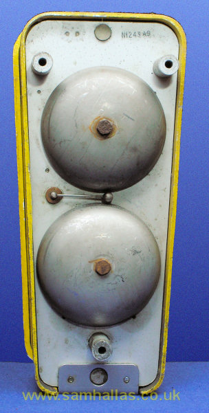
Now that the cover has been removed the screws holding the post adaptor can be removed to reveal the bell gongs and clapper.
As is usual the bell gongs are mounted slightly eccentrically to allow them to be adjusted by rotation for optimum ring. The clapper should be just clear of the gong when at rest. Too close and the clapper touches the bell tending to damp the ring: too far and the ring is weak or none existent. The gong screw heads are 0BA.
This telephone has now gone to a good home where it's been rewired to the original design and is back in working order. Here it is with a companion in its new home.
Back to where you left the main Post Hixon page
Photos & text © 2008 Sam Hallas.