
Sam Hallas' Website
Remarkably quickly after the Hixon Disaster Enquiry, Plessey produced a design for a system in 1970 which met all the requirements raised in the Enquiry.
Key features of the system are:

A single telephone in the signalbox provides all the signals and controls needed for communication with a crossing. Click for a larger image and Back to return.

Visual indications are a white CALL lamp and a red FAULT lamp
Audible indications are a buzzer for normal calls and a bell for emergency calls.
Controls are a single white CALL button on top and an Alarm Receiving Attention key at the front
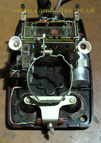
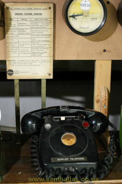
The telephone itself is a Telephone 710 CB fitted with a Handset No 7. The case has been modified to take the keyswitch at the front. The telephone transmission circuit is wired normally, but the bells are not fitted. A special bracket fits across the bell mounting holes to hold the keyswitch at the front. The neon light in the handset is wired across the bell. Click here to see the insides of the phone: and click here to see the way it appears on the block shelf with its instructions.
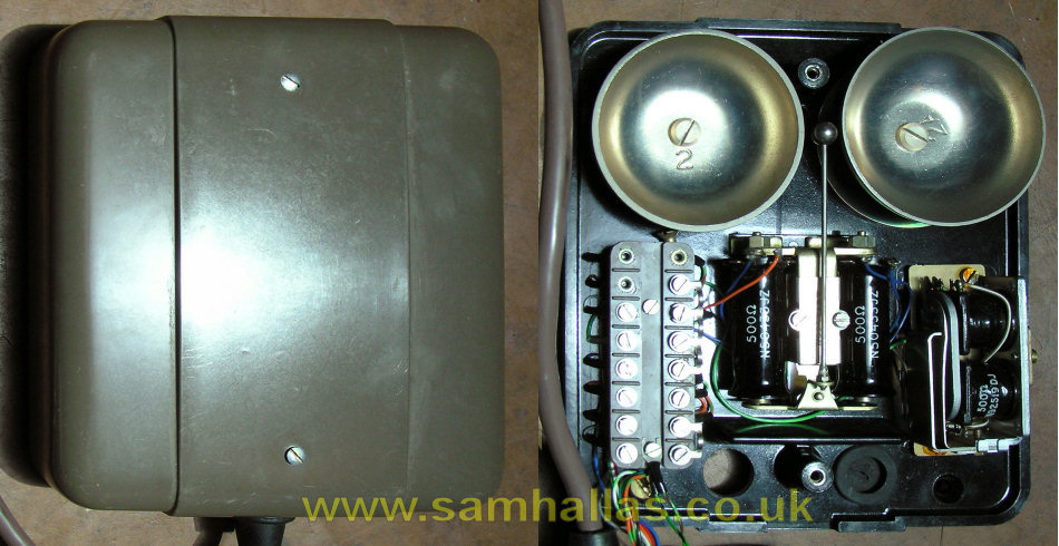
A separate box houses the bell and buzzer - see below. I assume that the bell gongs are mounted upside down to keep the height down. The buzzer is a magneto type as it is operated by AC ringing current.
The instructions for the signaller are shown left. Click for a larger image and Back to return. [card image: Andy Emmerson]

A complete crossing installation is shown above, pictured at Brodie Crossing, near Inverness in 2006. Notice that the emergency telephone is fitted on the offside of the road. The left hand telephone is obscured by the barrier. The other phone is fitted inside the barrier mechanism for use by technicians. Since about 1980 the advance roadside telephones have been removed.


The telephone is the standard Plessey weatherproof telephone body, similar to the BPO Telephone 745 CB. The bell is wired back separately from the transmission circuit. The main modification is an additional pair of wires in the handset cord which are connected together at the handset end. This allows the equipment to detect when the cord has been cut and raise an alarm accordingly.
The internal labelling dates from an initiative in the early 1990s (I designed and did the artwork for the labels) to aid clarity and to improve communication with the emergency services. The main label says "Lift Handset and press button for 5 secs to call". The name of the signalbox is supposed to be written underneath, followed by the location (name of the crossing) and the Ordnance Survey Grid Reference of the crossing.The label is mounted on a self-illuminated block - see below. The Dymo™ label on the handset is an unofficial modification but helps to reinforce the point about pressing the button.
This page has a more detailed look at the telephone
Press to Call: As something of an aside, here's what I understand is the reasoning behind the press to call arrangement. At some other crossings, magneto telephones were provided to call the signaller. By necessity these were press to call. The Department of Transport wanted all crossing telephones to operate in the same way so that a single instruction could be used in the Highway Code and in other information for motorists. It would have been possible to make the Plessey system lift to call, but for standardisation it was made the same as magneto telephones. This principle has been perpetuated in the subsequent PETS system - more of which later.
Beta-Light™: It is a requirement that the user instructions be visible at night. To meet this the railway adopted a piece of technology developed for military use call Beta-light™. The Beta-light contains small tubes filled with tritium gas and coated in a phosphor. Tritium is a mildly radiactive gas which emits beta particles (electrons) - hence the name Beta-light. The electrons stimulate the phosphor to glow providing a low level of illumination for signs. Because of problems with storage and disposal, radioactive light sources are avoided in civilian use these days, but are evidently still widely used in military applications (http://www.beta-light.com/ for more details). They require no power supply or maintenance and have a claimed life of 15 years, making them very suitable for trackside use. However, automatic crossings require a power supply to operate the barriers. Why the simpler solution of fitting a light bulb driven from the local power supply was not adopted we shall never know. The cap of the button marked Press is also luminous according to the Plessey handbook.
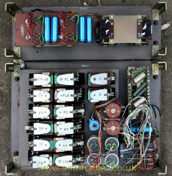
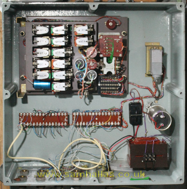
The signalbox equipment is mounted in relay cans: relays and ringing generator in one; tone and pulse unit in the other. It operates from a 50v supply. The crossing unit is housed in a massive aluminium casting about 470mm square by 165mm deep, sealed against moisture. It requires a local power supply of 24v. Left is a picture of a signalbox unit in Richard Pike's collection. Right is a picture of the crossing unit. Click for a larger image.
Idle: In the normal idle condition the loop in the telephone handsets is detected and a forward polarity (positive on the A-leg) battery is applied to the telephone pair back to the signalbox. Cutting a handset cord or breaking the line to the signalbox causes an alarm to be raised - the red lamp lights and the buzzer sounds. The signaller can silence the alarm by throwing the key on the front of the telephone. When the alarm is cleared the buzzer sounds again to remind the signaller to restore the key.
Normal call: The caller lifts the telephone handset at the crossing and presses the call button. A reversal (negative on the A-leg) is applied to the telephone pair back to the signalbox. The buzzer sounds and the white lamp lights. Ring tone is returned from the signbox control unit. The signaller answers by lifting the handset and pressing the button. Ring tone is disconnected and speech enabled. The call is held until the signaller puts the handset down.
Emergency Call: The caller lifts the telephone handset at the crossing and presses the call button. 25Hz ringing current is applied to the telephone pair back to the signalbox. The bell sounds and the white lamp lights. Ring tone is returned from the signbox control unit. The signaller answers by lifting the handset and pressing the button. Ring tone is disconnected and speech enabled. The call is held until the signaller puts the handset down.
Signaller calls crossing: The signaller lifts the handset and presses the button. 25 Hz ringing current is applied to the telephone pair to the crossing. The crossing control unit detects the ringing and applies its own ringing current to the crossing telephones. At the crossing telephone the user only has to lift the handset to answer. There is no need to press the call button.
Full technical details, with diagrams, are contained in the Plessey handbook for the system. There's a link to the full-size circuit diagrams in the next paragraph.
By about 1980, the requirement for telephones in advance of the crossing was relaxed and all calls were made to act in the same way. The circuit digrams (signalbox unit and crossing unit) show the modifications in pencil which dispense with the emergency call signalling of ringing current on the line. All calls make the bell ring at the signalbox. In 2024 Andrew Kenning from Network Rail found a set of the Plessey drawings and sent me these scans which include the auxilliary items such as ring and tone generators.
The system was designed to work with a metallic cable path from crossing to signalbox. As time went on, more and more remote signalboxes were introduced, covering large stretches of track, where transmission circuits were used and there was no metallic path between the two ends. A rather cumbersome relay set was produced which catered for this. The use of relays in the control units meant that skilled technicians were needed to keep them adjusted and working. With the demise of Strowger technology in telephone networks, these skills became increasingly rare.
Requirements occasionally arose where it would have been useful to carry other alarm signals back to the signalbox along with the telephone circuit. This was particularly true where there was no railway cable infrastructure and telephone pairs had to be rented from the Post Office. All these factors led in the mid 1980s to the instigation of development of a replacement system with the same features as the Plessey system and these additional features:
In case you missed the link earlier:
Taking the Crossing phone to bits
Acknowledgement: Thanks to Richard Pike for allowing me to photograph his collection.
Next: The Whiteley PETS
Photos (unless attributed) © 2006-2008 Sam Hallas.
Text © 2007 Sam Hallas.