
Sam Hallas' Website
Some of the items other than telephones that make up a subscriber's telephone installation.


This is where the telephone was connected to the internal house wiring, called in usual Post Office jargon "Blocks Terminal".
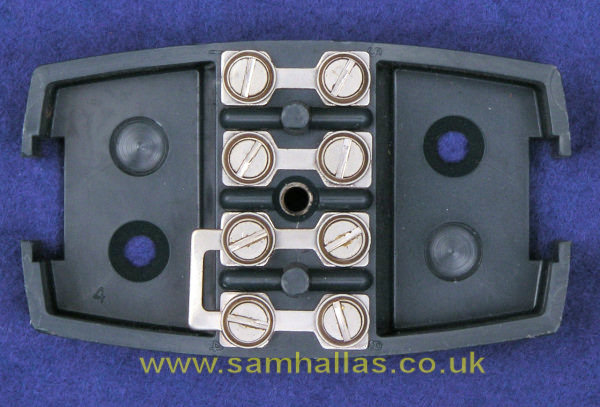
The terminal block supplied for use with the 700 range of telephones was available in colours to match the phone body. On the left are six of the seven available colours, grey, red, ivory, green, blue and black. Inside were either three (on early models, BT 30 above right) or four terminals (BT 52A below right). The spade terminals from the telephone would be on the right here and the house wiring on the left. The link was provided to connect the bell internal to the telephone in circuit. When an extension bell was fitted the link was removed and the extension bell wired in its place.
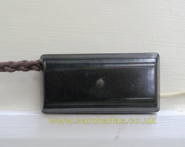
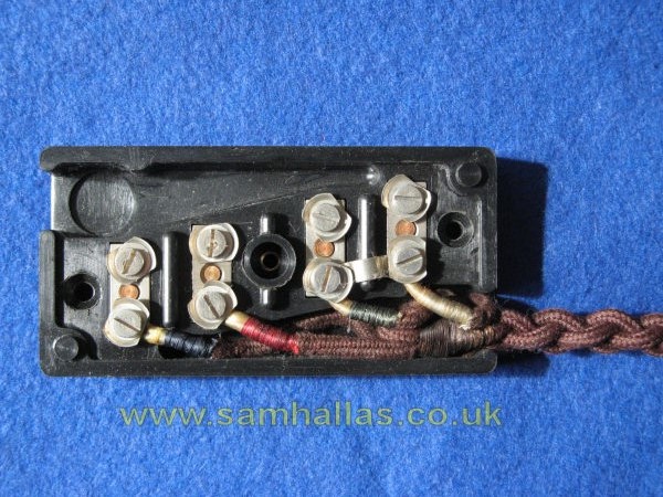
Terminal blocks before the 700 series era, were of the bakelite variety. Here's the four-way version for use with a 300 series telephone. Note the green and white wires are strapped together to complete the bell circuit.
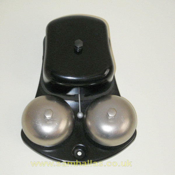
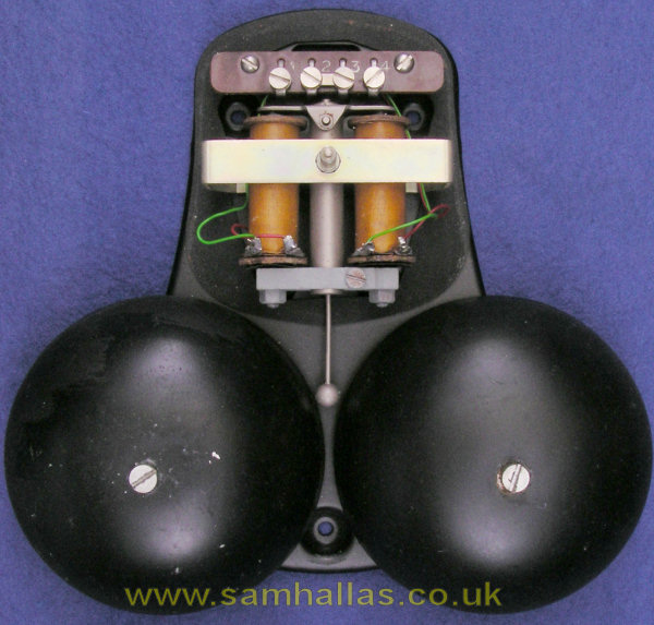
And here are a couple of extension bells which might be placed elsewhere in the building out of earshot of the bell in the main telephone. Both Bell No 64D and 64E could be used either inside or outside. Click here to see inside the cover - just a pair of coils and terminal block.
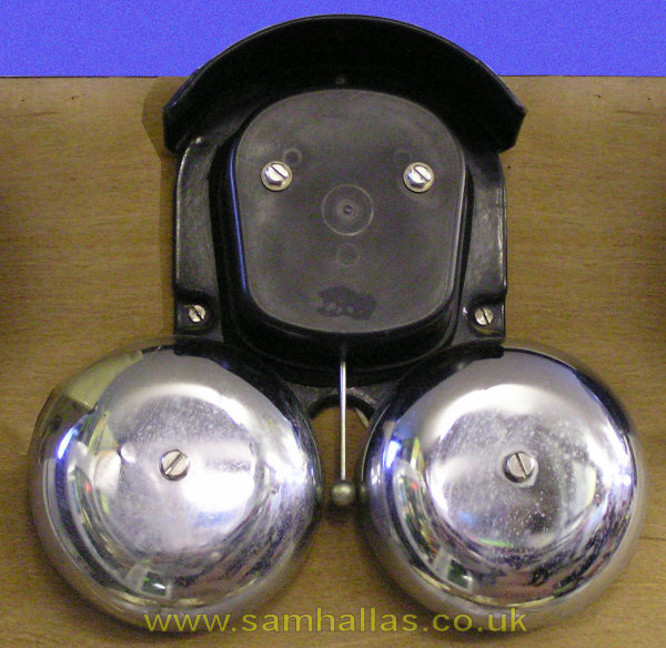
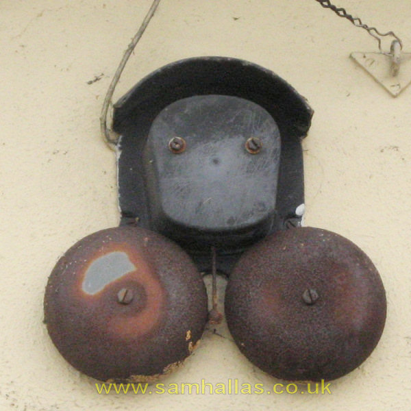
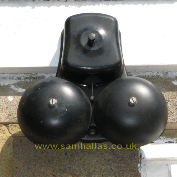
The Daddy of them all, the Bell No 67 was the bell used in preference for outdoors. It was loud enough to be heard across the yard of most businesses or down the fields on a farm. Left is a nice clean example at the Milton Keynes Museum. Right is one which has seen better days, fitted on a local garage wall.

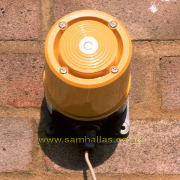
The Bell No 80 was the successor to the Bell 67 above for outdoor use. It still has two gongs, but they are concentric and hence the smaller one sits inside the larger one. Later versions had the high impedance coils used with the new plan plug and socket working. This is one I photographed for work to use in an internal catalogue.
The Tone Caller No 15 was an electronic replacement for the mains-powered hooter sometimes used in factories. It was line powered but none the less produced a prodigious level of sound. Hosiden-Besson called it first the Bedlam and later it was known as the Mayhem. This is another one photographed on the end of my garage for a work catalogue.
To hear what one sounds like try this video kindly supplied by John Hein - and mind your ears!
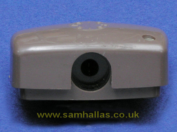
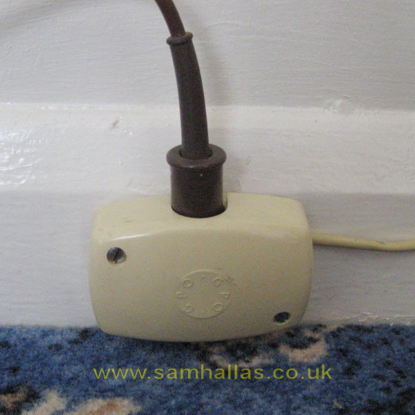
It was possible for subscribers to have an installation fitted with sockets and a movable telephone with a plug. The sockets were Jack 95A (left) for direct exchange lines with a Plug 420 fitted on the telephone cord (right). Diagram N4506 applies. Shared service lines needed an extra contact and so used Jack 96A and a Plug 505 on the telephone.
To prevent the line being left without a bell connected, the installation included a fixed bellset - typically Bellset No 26 below. By means of a break contact on the tip contact of the jack, plugging the telephone into the socket connected the telephone's bell in series with the one in the bellset.
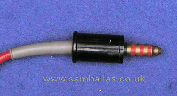
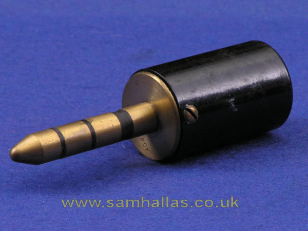
Early installations would have used Jack 65 and the much heavier Plug 404. Diagram N4306 refers.
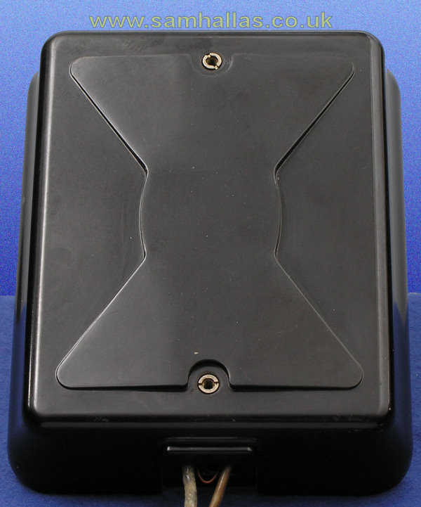
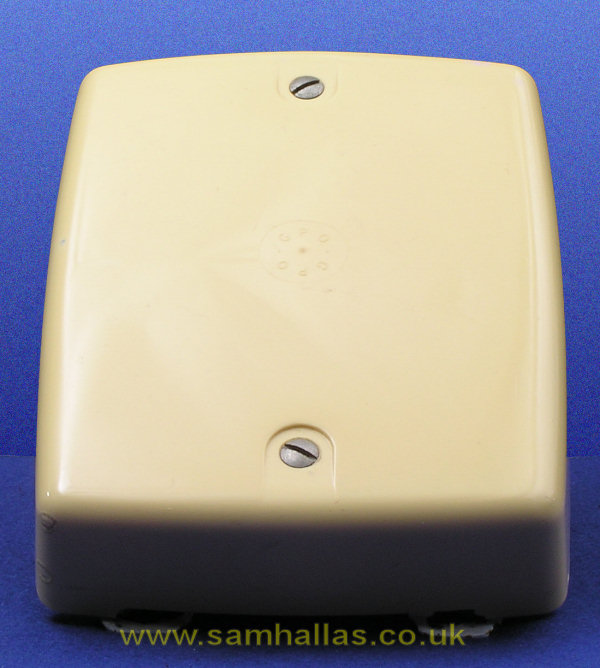
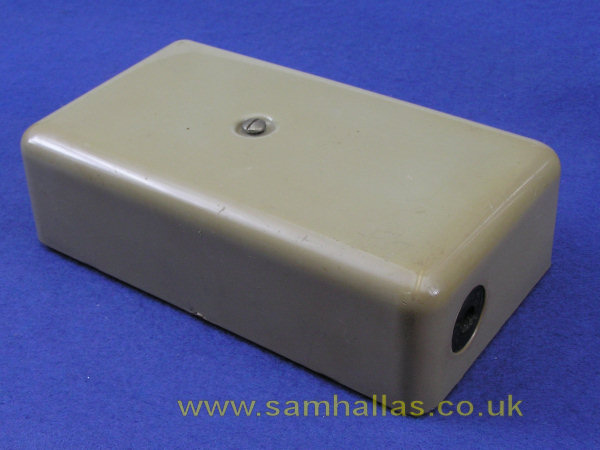
A Bellset comprises a bell with additional components. In this case it's simply a capacitor. Other bellsets may have inductions coils as well. Bellset No 26 could be used with telephones that didn't have an internal bell - such as the 200 series - or for applications such as the Extension Plan 4 above that required a separate bell and capacitor. Bellset 26 was originally fitted with a bakelite cover as on the left. Following the introduction of the 700 series of telephone at the end of the 1950s, a version with an ABS cover was produced, available in grey or, as on the right, in ivory.
The bellset on the left was donated by my local pub where it had been fixed high on a wall, probably since the 1930s. The interior was so stained with tobacco smoke that I had to wash it in soapy water. Click here to see the insides. That is indeed a piece of lead covered wire protruding from the base. The internal wiring is cotton covered. The more modern version has PVC covered wire but is otherwise identical inside.
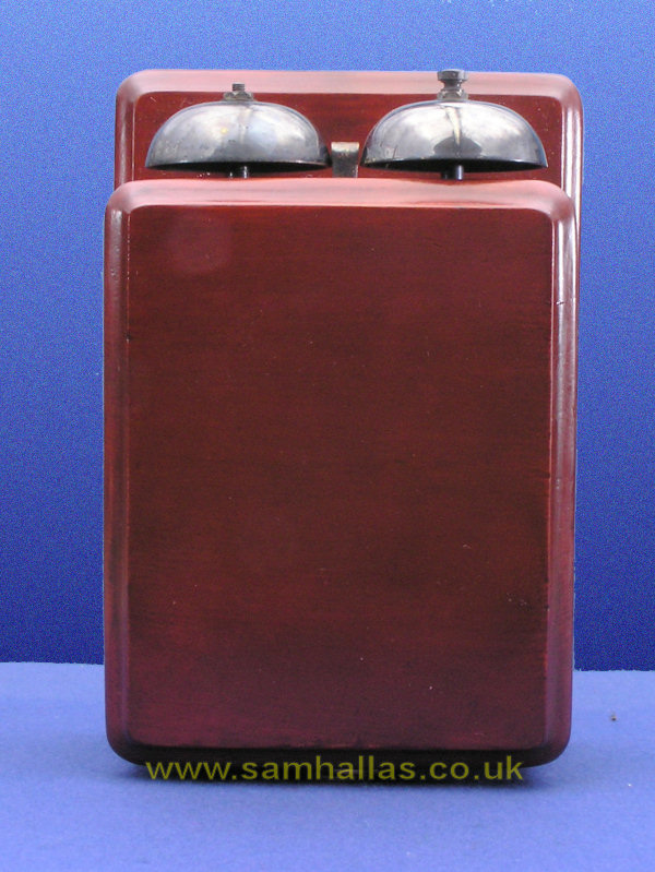
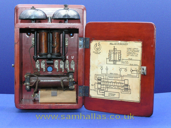
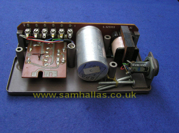
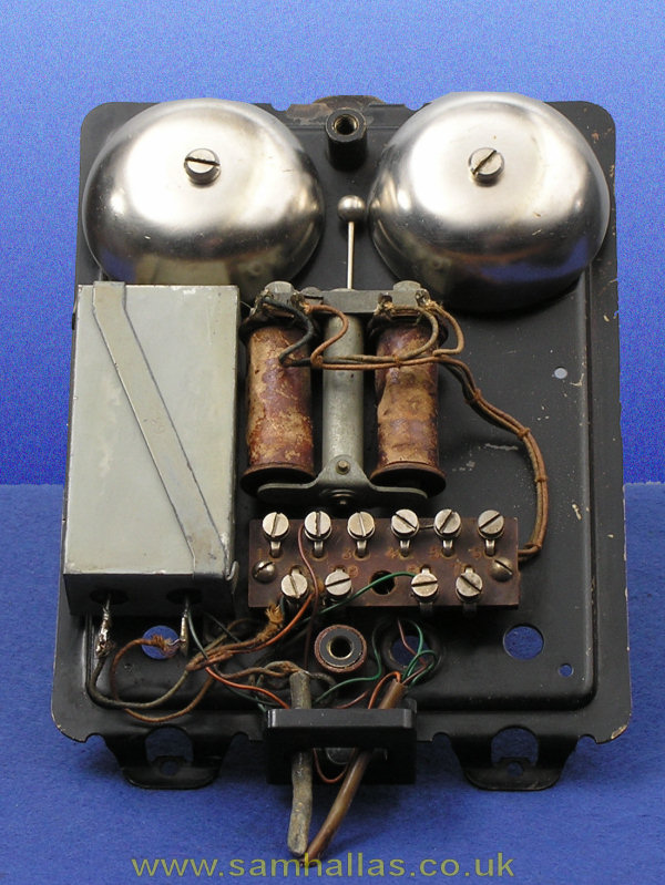
This is the bellset that goes with the candlestick telephone, Telephone No 150, and the early pyramid telephone, Telephone 162.
The circuit consists of the bell, at the top, the induction coil for the speech circuit in the telephone below it, and a capacitor at the bottom.
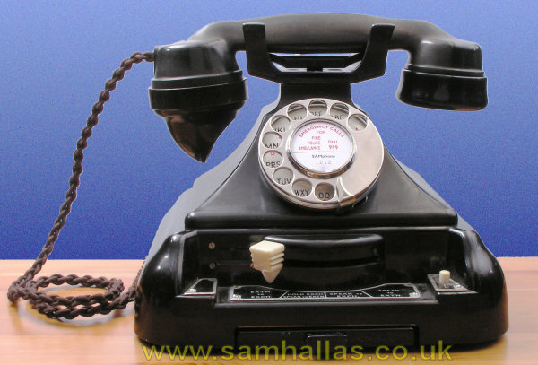
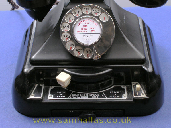
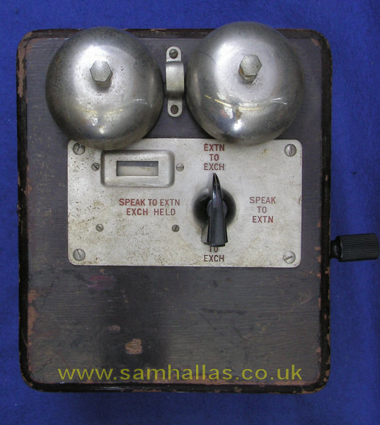
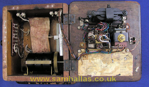
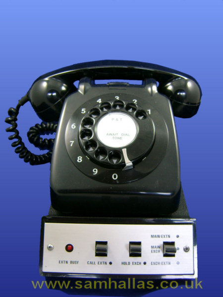
This is a much more complicated device than the previous bellsets and is the section beneath the telephone in the picture on the left. Bellset No 39 provides the switching and control for an Extension Plan 5 or Plan 7. This would typically be used in offices and small businesses as a secretary/ manager installation where one secretary answers calls for one or two managers. Provision is made for one or two press buttons - only one is fitted here - which give buzzer calling to each extension. An indicator just visible above the button shows when the extension is talking to the exchange line.
A typical call might run as follows. The secretary answers an incoming call with the switch in the 'Speak to Exchange' position. The secretary then switches to 'Hold Exchange, Speak to Extension' and presses the button to call the manager and announce the caller. Finally the secretary moves the switch to the 'Extension to Exchange' position allowing the manager to speak to the external caller. When the indicator shows that the line has cleared, the switch can be returned to 'Speak to Exchange'. An intercom is provided to speak to the extension without busying the exchange line.
Perversely Bellset 39 does not contain a bell. Unfortunately this bellset had been stripped of most of its components to make some sort of model railway controller. Bellset 39 superseded Bellset 20 (see below). In turn it was superseded by Planset N625.
The predecessor to Bellset 39 above. Notice that this one DOES contain a bell. The indicator shows when the extension is engaged as on the No 39. Calling is done by ringing the extension bell with the magneto whose handle is on the right. This model has been rebuilt from the earlier Bellset No 7 and is stamped as such on the back. It also has a rubber stamp saying 'P&T 20' so is likely to have been rebuilt by the Irish P&T at the St John's Road factory, Dublin. John Mulrane tells me Bellset 20s were used in Ireland right up to the end of the period where equipment was rented. It was found to be the most flexible and suitable for the Irish market.
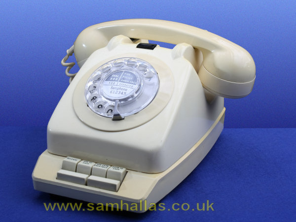
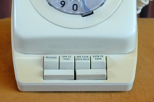 The successor to both Bellsets 39 and 20. An installation consisted of the Planphone plus one or two extensions. Exchange calls can be answered on the Planphone and switched through to either extension. An intercom feature allowed a private conversation between the Planphone and one or other extension. Details of the buttons on the Right. Instructions on using the main phone are in this document.
The Planphone was made up of the Planset N625 as the base with a Telephone No 706 with modified wiring mounted on top. A local 10 Volt power supply was also needed to complete an installation.

The Irish P&T continued the manager secretary development with this unit from Lake Electronics. Introduced about 1978 and supplied up until the end of the rental era. There may even be some still in service. It was never adopted by the British Post Office. Thanks to John Mulrane for the pictures and information.
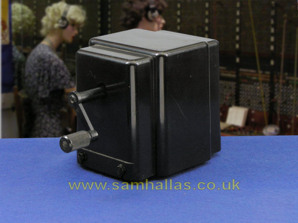
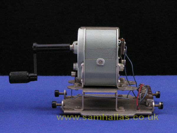 A magneto generator, Generator No 26 AN, in its own separate case. It might have been used with a small switchboard or on a Plan 5 or 7 with external extensions.

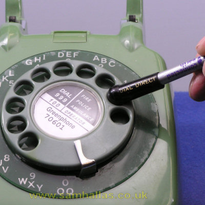 These little plastic gizmos fit on the end of a pencil to use instead of a finger when dialling - as seen on the right. They were generally issued to PABX switchboard operators as well as public exchange operators - people who spent much of the day dialling numbers.
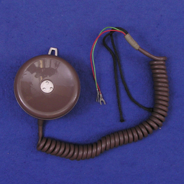
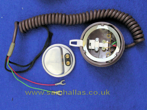
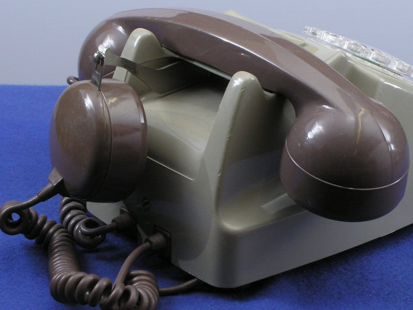 A second receiver could be used for a second person to listen to a call whilst taking notes. Alternatively those with hearing disability find it an advantage to use both ears on a call. Brackets were available for Telephone No 706 and (as on the right) Telephone No 746. The hook it hangs by switches it off when it is parked on the bracket, stopping it reducing the volume on the main receiver when it is not in use. See this picture of the insides to see how it works
 A small self-contained switchboard for use in shops ans offices. It came in several sizes. This is the PMBX 2/2A with 2 exchange lines and 6 extensions, described as 2+6. Others were 3+12 and 4+18. An even larger version at 5+25 was available for mounting in a customer's own furniture. The only additional equipment needed is a 50v power supply. Extension phones must be fitted with an auxiliary switch hook contact and a desk cord with an additional conductor. The operator used a standard 700 series telephone which could be wired diretly into the switchboard.
The calling indication was usually provided by a Buzzer 33A discreetly mounted under the desk somewhere. It gave a characteristic honking sound when the switchboard needed attention.
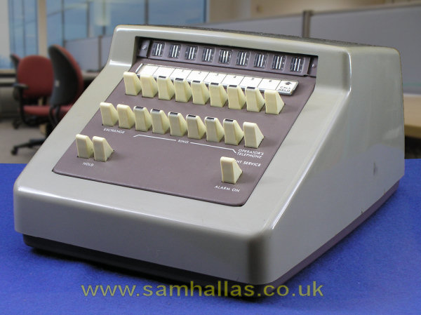
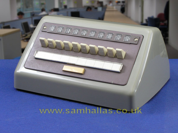 The Key and Lamp Unit 2A was designed for use in call centres to terminate up to 10 incoming lines. The Post Office called this 'Order Table Working'. Unlike the switchboard above, it is not self contained. It contains only the keys and lamps visible, together with a recall button and an optional sounder. It would typically be used with a Jack Unit 1B and Headset No 1 to provide the operator with speaking facilities. Alternatively the pendant Tele 713 below might used. A drawer dial - see below - might also be fitted. External lines would be terminated on Units Auxiliary Apparatus mounted on racks in a separate equipment room. These allowed it to be used with standard exchange lines or a variety of private circuit types. A larger model, No 10A, was available with 20 keys in two rows.
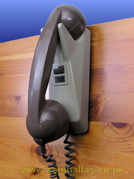
A typical use for the pendant Telephone No 713 would be in association with the Key and Lamp Unit above in a call centre. It can be mounted on any convenient sloping or vertical surface. There is no speech circuitry in the Tele 713, only a cradle switch with various contacts and a press button. The speech circuits are contained in a unit such as the Bellset No 50B below.

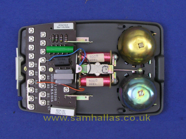
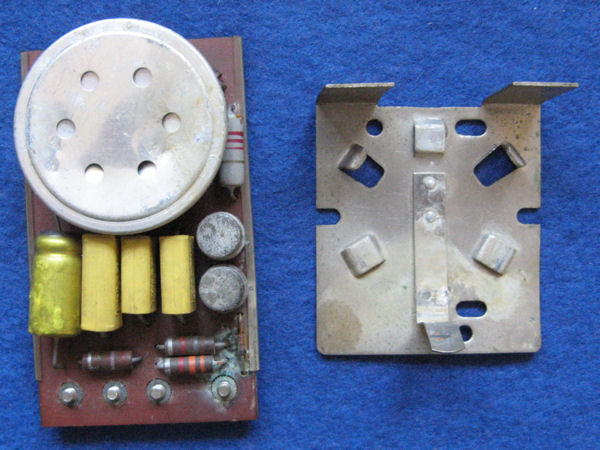
The Bellset 50B complements the pendant phone, Telephone No 713 above, by providing the speech circuit needed to make it work. Inside, on the right, you can see that it's pretty much a Telephone No 746 in a wall mounted box. The back is provided with the same T-shaped bracket used to support the Telephone 711 and 741 wall phones. The variants 50A and 50C contain only a bell and capacitor with no speech circuitry. The A version had the older 1000 ohm bell: the C version had the newer 4000 ohm bell for use with the New Plan Wiring scheme.
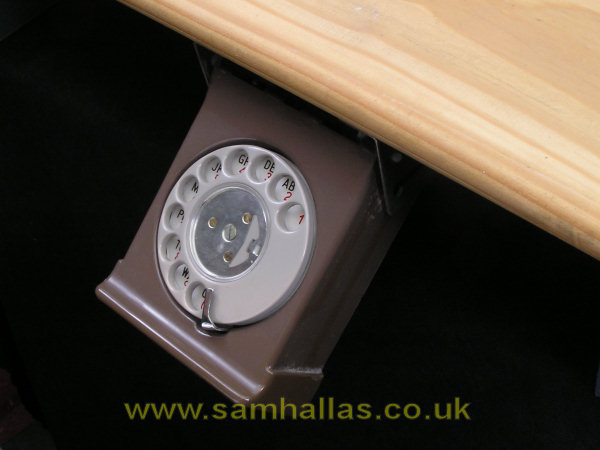
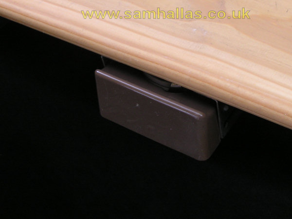
The pendant telephone installation is completed with the addition of this drawer style dial. Mounted under a desk it pulls out for use (left) and folds away (right) when not needed.
Another item that could be used with the Key and Lamp Unit. The Jack Unit 1A contained the circuitry of a 700-series telephone fitted with a Jack 84A allowing a Headset No 1 to be used to make and answer calls. It would usually be mounted out of the way in the knee hole of a desk.
Next some exchange and testing items.
 Private
Test & exchange
Private
Test & exchange