
Sam Hallas' Website
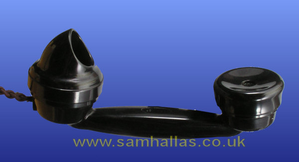
Quaintly designated as a 'Hand Microtelephone', this handset started the bakelite revolution for the Post Office. Originally associated with the Telephone No 162 it saw service from the late 1920s through to the end of the 1950s and beyond.
By 1931 the performance of its predecessor, Telephone No 28 - as seen in the previous article, was causing concern to the Post Office. Poor speech caused a recommendation to replace the old design with Tele No 164 - See Reference 1.
Telephone No 164 made use of insets for both transmitter and receiver as will be seen below.
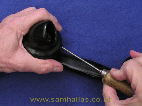
The mouthpiece is held by a steel ring with three projections. To release it pressure needs to be applied through the small hole at the handle side. A good tool for this is a drawing pin with the point filed off. I usually use an old bradawl. (Fig 2). Press inwards and turn anti-clockwise to release the mouthpiece. The transmitter inset can then be removed (Fig 3).
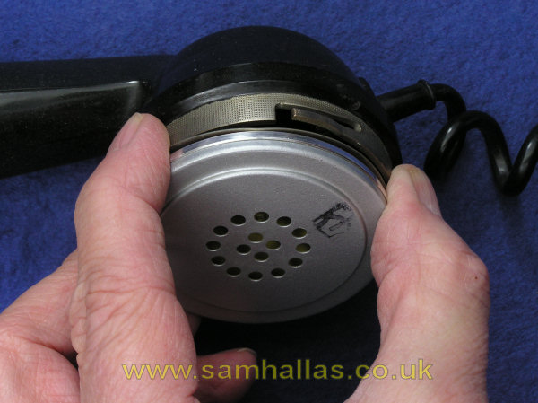
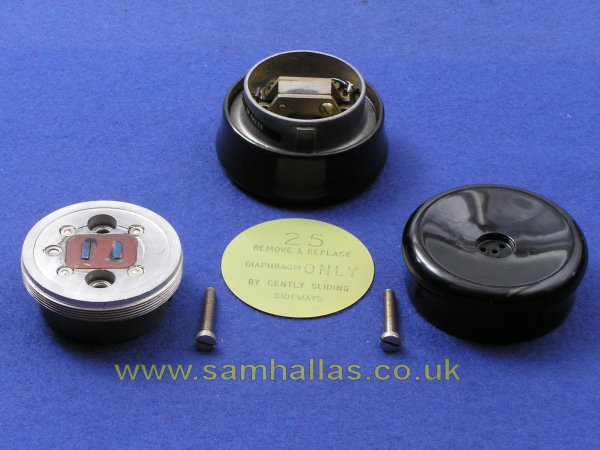
Unscrew the earpiece and slide the diaphragm gently to one side. The two retaining screws can now be removed to release the receiver inset.
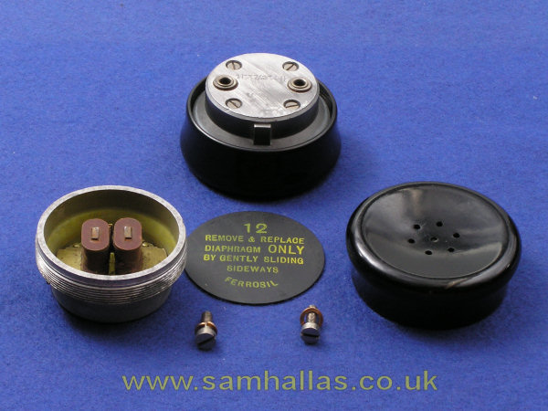
Early handsets used Receiver Inset No 1L: later ones used Receiver Inset no 2P. They are electrically and mechanically interchangeable, but the diaphragms and earpieces are different. Left: Receiver Inset No 1L with diaphragm No 12, Earpiece No 18 and short 2BA screws. Right: Receiver Inset 2P with diaphragm No 25, Earpiece No 23 and long 2BA screws.
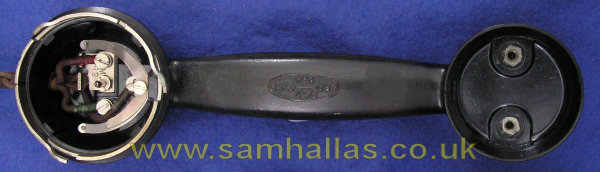
Once the insets have been removed the bare structure of the handset is revealed. Notice that there is no visible internal wiring. All the interconnections are contained inside the bakelite moulding. Only three terminals are provided since the telephone circuitry of the Tele 162, the 200 series and 300 series used a common connection between the transmitter and receiver, labelled MR. (Ref 2)
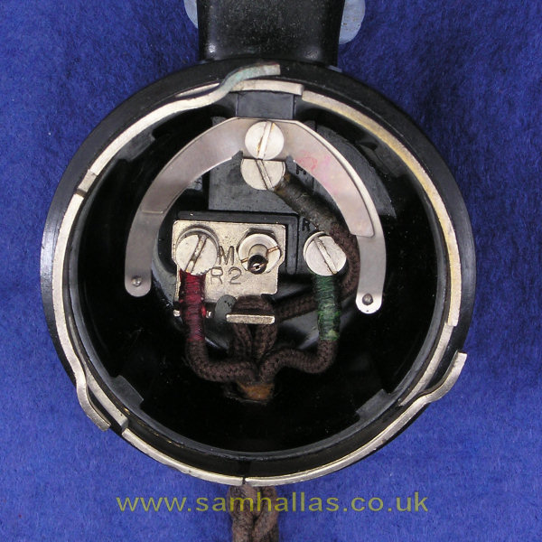
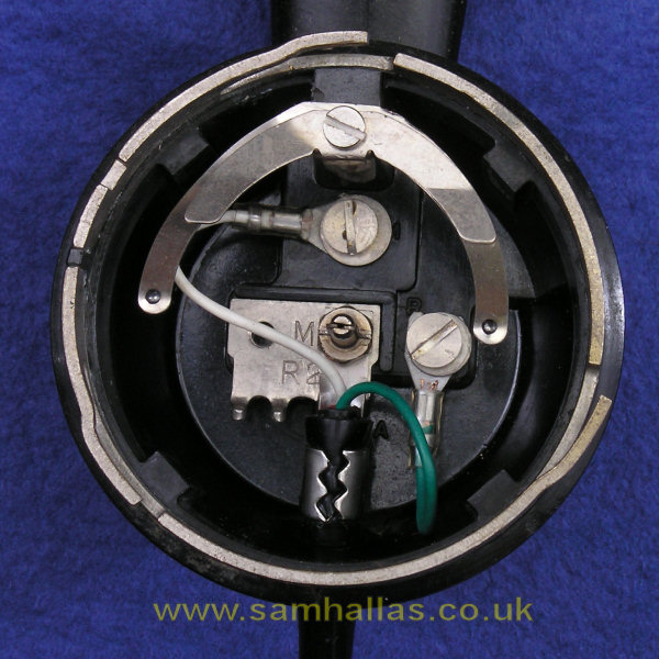
Because of the Tele 164's longevity it was used with a variety of cords. The method of anchorage was changed to match the cord. On the left is a braided cord with the fabric loop slipped over the tab on the MR terminal. On the right is the way the straight plastic and curly plastic cords were anchored using a metal tab, linked to the red wire, under the transmitter bottom connector.
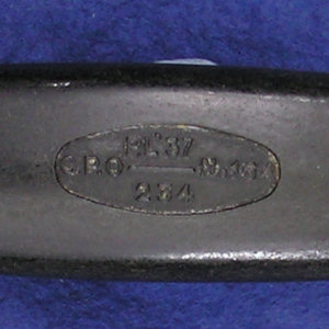
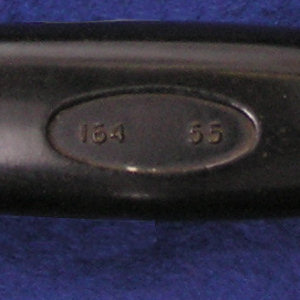
The manufacturer's mark is contained in an oval window on the inside of the handle. The earliest I have is dated 1937 (left) and is fairly verbose, reading "P.L '37 G.P.O. No 164 234": later ones are more terse like the one on the right which reads simply "164 55"
1. Telephone Efficiency Committee: Report on Local Battery Areas, May 1931 www.britishtelephones.com/reportlbareas.htm .
2. Circuit diagrams N262, N332, N432
 Tele No 28
Handset No 3
Tele No 28
Handset No 3