
Sam Hallas' Website

Telephone No 741 is the wall-mounted variant of Telephone No 746.
Although internally it is similar to the 746 a number of changes needed to be made to turn the structure through 90 degrees.
[Click the small images for a pop-up larger version]
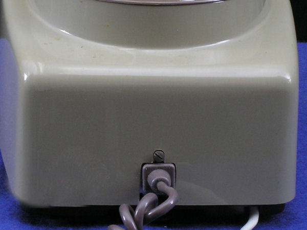
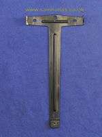
The cover is retained by a single screw as on the table model (Fig 2 left). However, in this case the screw needs only to be loosened until the head is clear of the groove in the case. The cover can then be lifted away from the base. The shape of the screw can be seen in Fig 4 below.
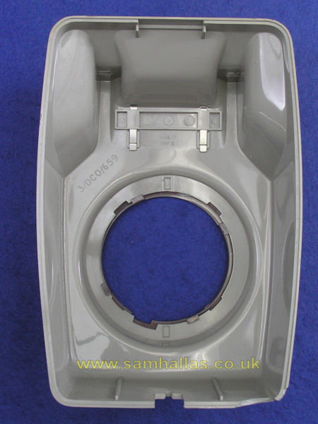
The cover is nearly identical to its predecessor for the Tele 711 [Ref 1]. So much so that the press buttons and support assembly for the switches are the same. See N849. for details. The blanking plate is held in by the spring clips seen in Fig 3, right. I'm sorry I don't have a 741 with buttons to show you. The rebate described in Ref 1 can be seen around the inside of the cover
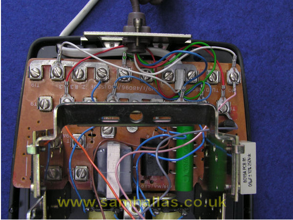
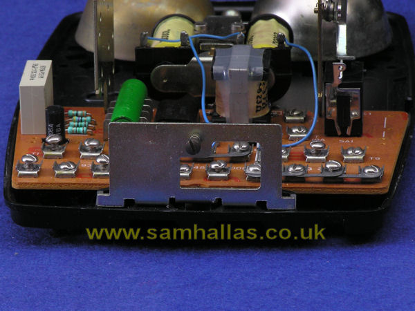
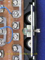
This is a Telephone No 8741, meaning it has a 4000 ohm bell for use with the modular plan wiring scheme and has a plug ended cord. Being dated 1983 and from Plessey it has a plastic base. Diagram N8841 shows the circuit. Note other differences are that capacitors C1 and C2 ore omitted and MR2 is soldered into the circuit board. The differences can be seen in Fig 4, left, and the rather improvised way that the plug ended cord is secured by trapping it under a strapping link. The cord is threaded through the extra hole in the case also used for the watch receiver.
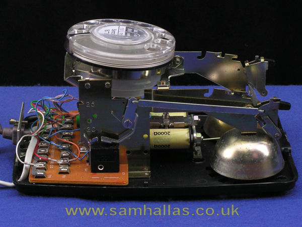
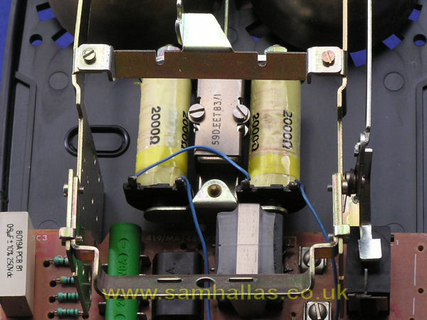
Once the cover is removed the extent of the mechanical changes becomes evident. The main bracket has arms extending as far as the bell mounting holes where it is screwed down. The bells are fixed to moulded supports by 4BA screws with nuts on the underside of the case. This is the same arrangement used on plastic cased Teles 746. The nuts are moulded into the plastic but not very securely.
The fixing bracket for the case screw also serves to retain the handset cord grommet. The hole is shaped so that the grommet can be relased by sliding it sideways. Fig 6, above left
The dial mounting brackets are fitted between the arms with 8BA screws into tapped holes. Fig 7, above right
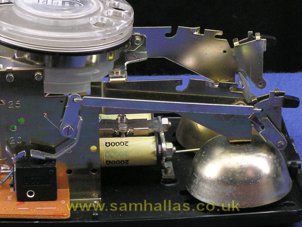
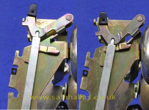
The polythene cradle rest pips are pivoted onto the main bracket extension arms and joined by a steel plate. They push down on a long rod that rotates a short arm held by a coil spring. This arm is joined to a short lever which operates the hookswitch. See Fig 8, above left. A means of latching the telephone on-hook whilst the cover is removed is still provided as seen in Fig 9, above right. Left is the normal postition and on the right the cradle is latched. The latch is released by pressing the cradle rest down and letting go.
Telephone no 741 hangs on its wall bracket by two hooks fitting into slots on the telephone base. Fig 10, left. At the bottom it's fixed to its wall bracket by a single screw. The circuit board has a semi-circular notch to allow easy access by a screwdriver. And, yes, that notch was there in the board inside the Tele 746 but I didn't notice it. Fig 11, right Two pegs moulded into the case lift the bottom clear of the wall.
In my desire to live up to the title of the series I made the effort to dismantle the Tele 741 as much as I could.
You may have wondered how the bells can be removed with the main bracket where it is. The answer is with difficulty. I had to remove the centre dial bracket and bend the main bracket slightly to allow a bell to slide out along with its washer. It proved nearly impossible to get it back again, especially once the nut fell out of its moulding in the base.
This led me to the conclusion that the bells were probably put in place before the main bracket was riveted onto the base.
I also took the cradle rest mechanism apart by removing the screw holding the pivoted bar, detaching the push rod and lfiting the cradle assembly off its pins. Again it was difficult to put back. A blob of Blu-Tack® was need to hold the cradle rest in the off-hook position before I could screw the pivot screw back.
A correspondent has advised my that he has a Telephone 741 that has a different mechanical construction. It is easier to dismantle. The side members of the main bracket are not rivetted in place. The bracket for the handset grommet and case screw is an integral plastic moulding.
Telephone 741 was the last Post Office design purely for wall mounting. Later telephones, such as the Statesman were dual purpose in that they could be wall mounted with a suitable bracket.
The Telephones 746, 740 and 741 were the last of the mass-market non-electronic telephones. However the 700 series circuitry had one last fling as the basis of the Compact Telephone, Telephone No 776.
1. Telephone No 741 & 8741 at Britishtelephones.com
http://www.britishtelephones.com/t741.htm
 Tele 740
Project Index
Tele 740
Project Index