
Sam Hallas' Website
The fifth in a series of articles where I dismantle a telephone to show its construction and pass my own opinionated comments on the design and choice of material.
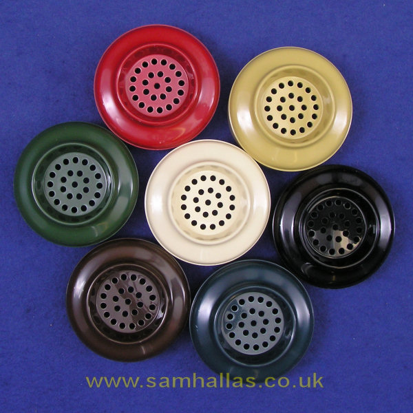
This article was written in the 50th anniversary year of the Telephone 706. Launched in 1959 Tele 706 replaced the 300-series telephone which by then looked decidedly dated. A change of material from a pressure cast phenolic resin to an injection moulded thermoplastic meant that the 706 could be supplied in a range of attractive colours beside the utilitarian black of earlier models. All seven colours can be seen in this kit of spare mouthpieces.
The design drew inspiration from various telephones already in service from Ericsson, Siemens, and AT&T, and most definitely from the Automatic Electric AE80. In addition to the innovative case design, the internal circuitry made use of advances in technology to provide improved speech transmission. So everything about the 706 was new: new case design; new handset; new dial; new transmission circuitry; new cordage and block terminal.
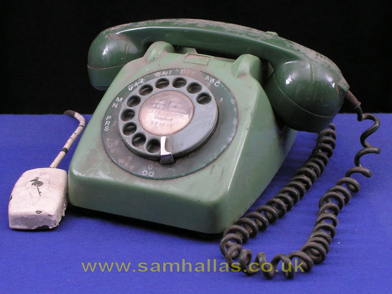
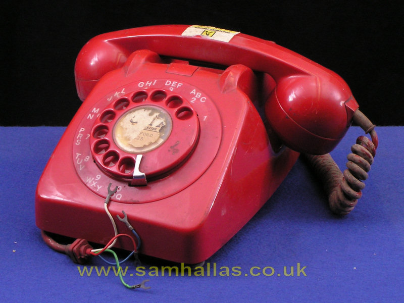
Let's meet our candidates for dismantling. They are Mr Green and Mr Red. I bought them specifically for this project because between them they provide examples of different elements of design. 706s were produced in a hard-wired version and a printed circuit version. The wired version is called Mark I and the printed circuit version is Mark II, although both were produced simultaneously depending on the individual manufacturer's preference.
Mr Green is a wired model and Mr Red is a printed circuit model. They are seen here in an 'as found' condition having been recovered from site and left in store for maybe thirty years.
[This is not going to be a study in restoration, but once they were dismantled I cleaned them and you can see them restored to their full splendour. That's the green one above. You can see the red one at the bottom of page 3]
I'll take apart the new handset, Handset No 3, to look at the new receiver and transmitter inserts. I'll show pictures of the new cords and terminal blocks, BT30 and BT52A. Finally I'll look at some examples of auxiliary parts that can be added to the Telephone 706 in order to show off the versatility of the design.
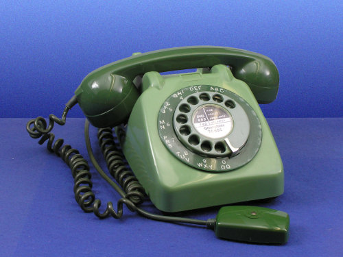
Despite the dirt you can see from the pictures that the case has a pleasing shape with smooth curves and the dial has a comfortable angle. You'll not be surprised to hear that the Council of Industrial Design had a hand in the design. The use of a thermoplastic injection moulding speeded up the moulding process considerably, making the 706 cheaper to produce. The original choice of material was polymethyl methacrylate, which ICI called Diakon, but everybody else calls Perspex, a plastic first developed in the 1930s. It retains its lustre well and the colours do not fade. However it is fairly fragile and there were many breakages in the early years. Diakon was replaced by about 1962 by ABS, (Acrylonitrile butadiene styrene), which is more resilient, but with age becomes less shiny and the colours tend to fade - especially the ivory and blue. [Ref 5] ABS was a spin off from military research during WWII. It has now become the standard material for appliance case mouldings, but in the early 1960s was only just beginning to be widely used. More on the case material on the Telephone Files page
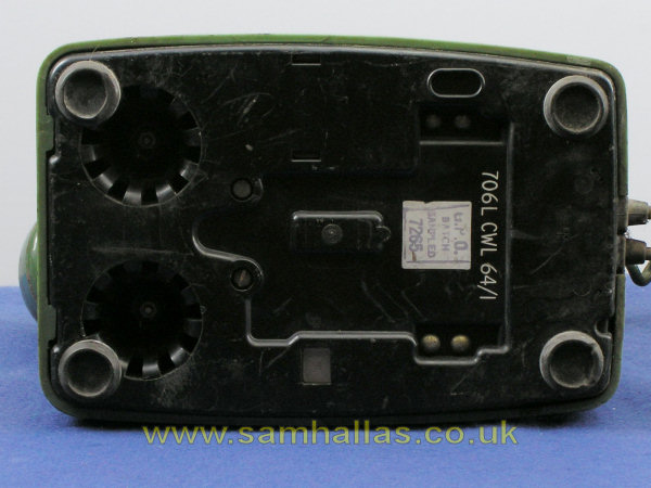
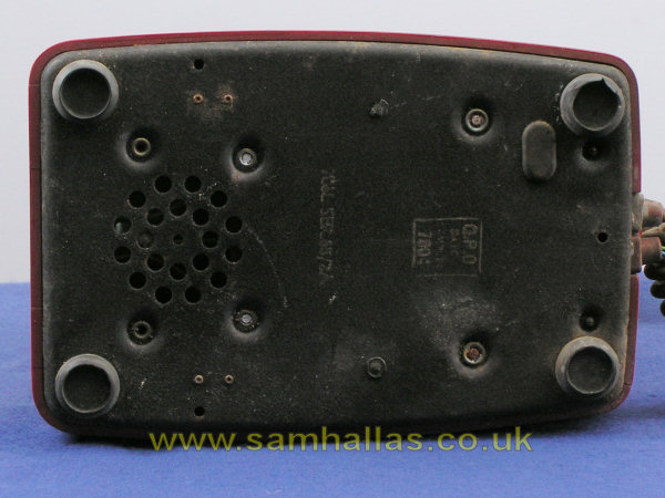
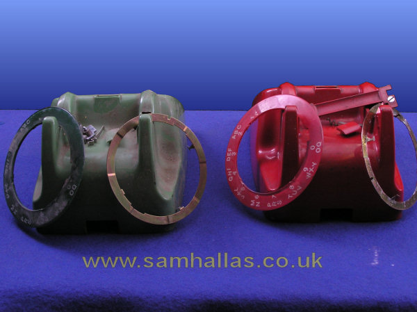
Let's turn the phones over and have a look at the bases which shows the difference in the two styles of construction very clearly.
The green phone (left) has a thermoplastic base made from toughened polystyrene. This is a good choice of material being resilient and virtually unbreakable. The hollow circular areas to the left are the supports for the bell gongs.
The red phone (right) has a pressed steel base with a crackle paint finish. Again steel is a good strong material and resistant to damage. The bases of six rivets are visible which support the bell pillars and circuit board.
Notice that both bases have an elongated hole top right in the picture. It is filled with a blind grommet on the red phone. This hole has been provided to allow wiring to be routed out of the base for applications such as the Planphone A.
The feet are made from a synthetic rubber, usually called Neoprene, which does not harden as readily as natural rubber. So, despite their age, the feet of these two telephones are still fairly springy. Early versions of the 706 had domed feet. [ref 1] These proved unsatisfactory as the phone skidded about during dialling. Later models have the ringed feet like these which act like mini rubber suckers and help prevent skidding. [Ref 5]
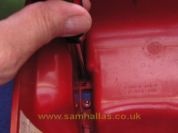
The markings on the green phone are are 706L CWL 64/1 Meaning as follows: 706L - a telephone No 706 with a lettered dial - CWL - made by Pye at Cambridge - 64 - made in 1964 - /1 - Mark 1, ie a wired version. The markings on the red phone base are 706L SER 65/2A. 706 - as before - SER - made by AEI, West Hartlepool - 65 - made in 1965 - 2A - Mark 2A, ie a printed wiring version. See this page for more manufacturers' codes.
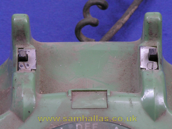
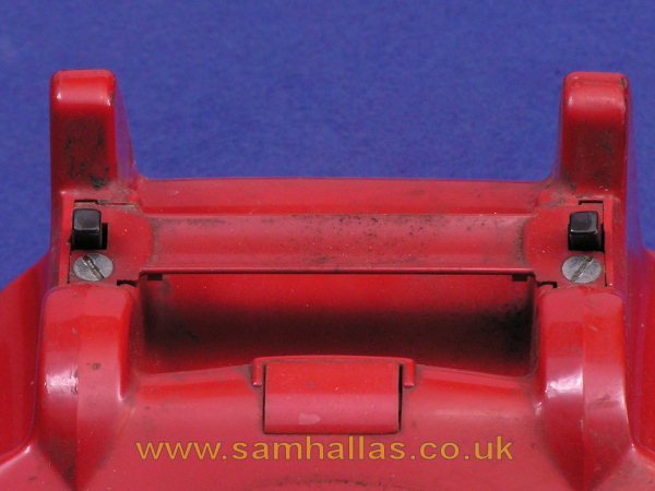
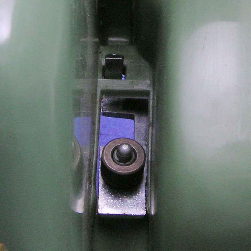
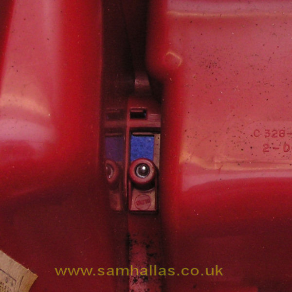
The green telephone has the original chrome escutcheons around the cover fixing screws, whereas the red phone has the optional carry handle. Both the telephones have a blanking plate in the hole provided for a push button switch.
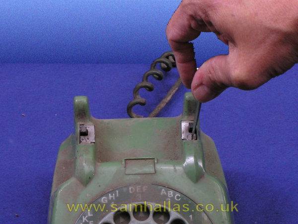
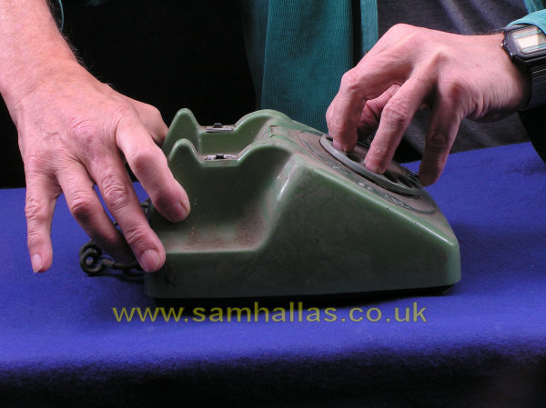
Remove the cover by loosening the captive screws. Do I need to mention again that I approve of captive screws? Lift the cover away from the body. Hold the body still by placing your fingers in the dial with one hand. Pull upwards and forwards on the cover with the other hand. (Yes, I've worked out how to use the self-timer to take pictures with both my hands in shot.) You don't need to see me take the lid off the red one as well, do you? If need be the captive screws can be released by pulling upwards and turning anti-clockwise.
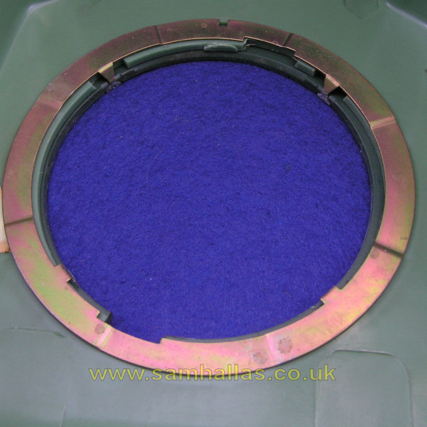
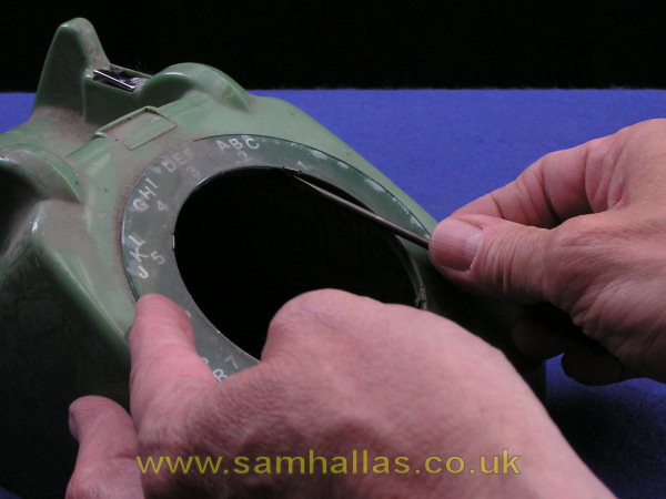
By turning the cover over you can see how the dial number ring is held in place by the small lugs on the steel ring. I find this fixing unsatisfactory as it tends to come apart every time I take the lid off. If it hasn't already come off, gently prise one lug outwards with the blade of a small screwdriver whilst pulling the ring away from the case. You may find this easier to do from the other side of the case.
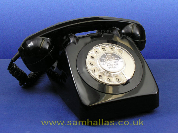
The number ring is clear and the numbers and coloured background are silk screened on the back. This has not proved very durable as the ring shifts slightly in use and tends to wear away the printing. The red one is particularly badly affected. Later dials, like the one on the black phone below, have a clear plastic finger plate. The numbers are printed behind it, where there is less chance of them wearing off.
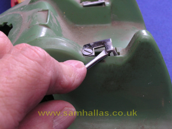
With the cover turned over you can see how the metal escutcheon and the carry handle are held in place. The escutcheon can be removed by levering gently with a screwdriver from above. The carry handle needs only light pressure with a screwdriver from below to avoid breaking its lug. The Post Office TI recommends straightening the escutcheon lugs and you may want to do this before refitting the escutcheons as they can be reluctant to go back.
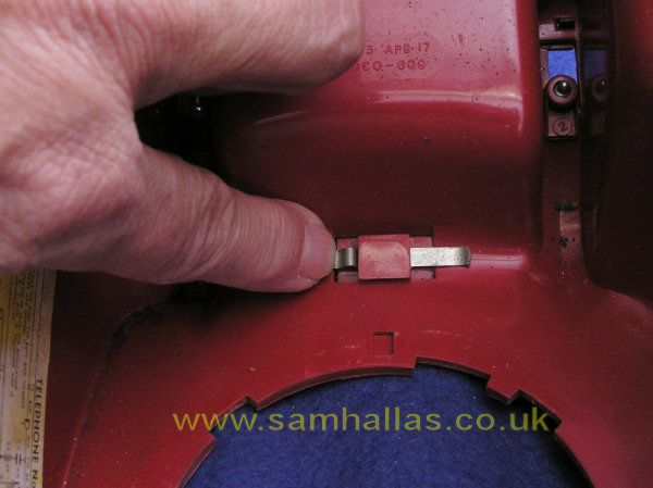
The button blanking plate can be removed by sliding the retaining spring out with a finger. The cases are now dismantled ready for cleaning.
Reassembly is straightforward. The dial ring is a bit fiddly to get in position. First line up the lugs on the metal ring with the indentations in the plastic rings, then squeeze the two together. There is a cut-out to fit round the dial finger stop on the case, the dial ring and the steel fixing ring, which must be aligned on reassembly.
