
Sam Hallas' Website
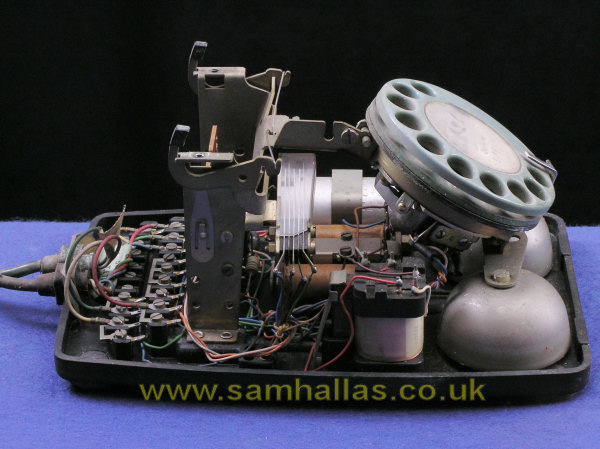
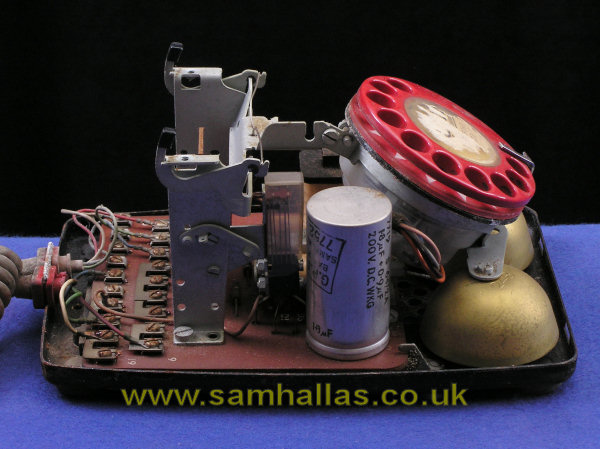
With the cover removed it's easier to compare the two models. There are similiarities - all the circuit components are the same - and differences - their positions are different.
It also now becomes plain that the red phone is in a sorry state. It looks as if it's been submerged at some time! Many of the steel parts are rusty - more than just storage in a damp place would cause.
I understand that some telephones released as scrap have had the capacitors removed. This is due to a belief that they contain poly-chlorinated biphenyls (PCBs). This is almost certainly true of the tubular paper capacitors used in Telephone 706 but is almost certainly not true of the polycarbonate capacitors used in later telephones.
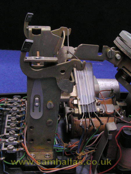
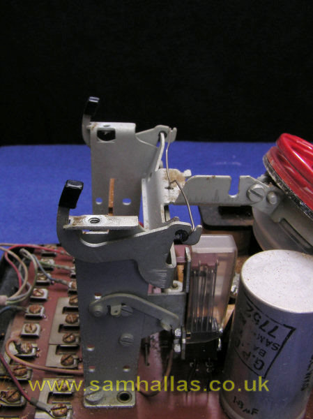
The hookswitch mechanism is a natty piece of design. Firstly the polythene stubs which protrude at the top are designed to be noticeably smaller than the aperture so there is no danger of them sticking. The knife edge pivot eliminates the sliding peg designs of previous telephones, also aiding the non-stick design. The single bow spring is simple, cheap and unlikely ever to wear out.
On the side of the case support pillar is another neat feature of the 706. The spring clip on the green phone and the swinging lever on the red phone allow the hookswitch to be latched on-hook so that the phone can be serviced at a customer site without busying the line.
The switch itself is well-designed using a plastic comb to operate bifurcated contacts allowing consistent spring pressure (below left). The plastic cover keeps dust from falling between the contacts. The only difference in the two models is the mounting and terminals. They both use the same fixing holes on the case support pillar. You may think that the steel bracket on the printed circuit version is unnecessary. However, I think that it stops any tendency for the cradle rest mechanism to rock the contact assembly and loosen its solder joints.
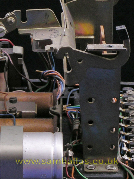
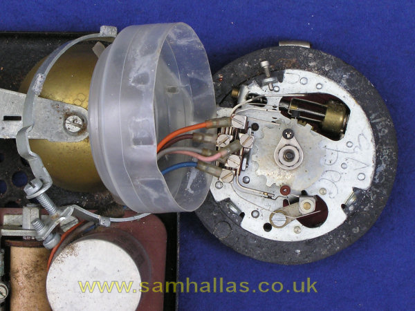
While we're looking at this portion of the 706's construction, notice that the case support pillar is pre-drilled with all the fixing holes that may be required for accessories. (above right) This means no need for multiple variants in stockholding or on-site drilling. Everything bolts into place.
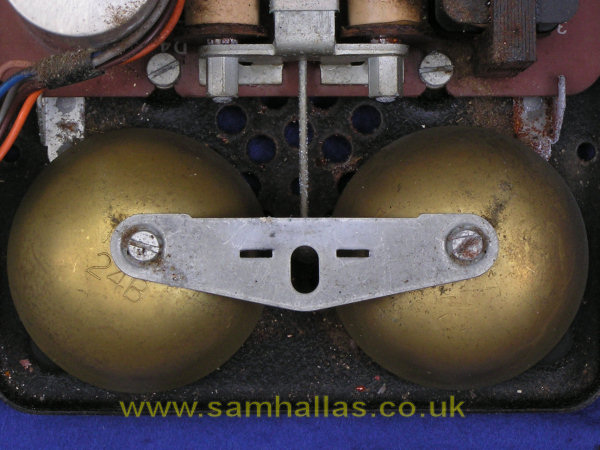
The case support pillar pressing has an extension which forms the rear fixing for the dial mount. Versatile isn't it?. The rear 4 BA screw releases the dial mount which then tips forward and lifts clear. The front fixing is a bracket with slots that fits across the bell gongs.
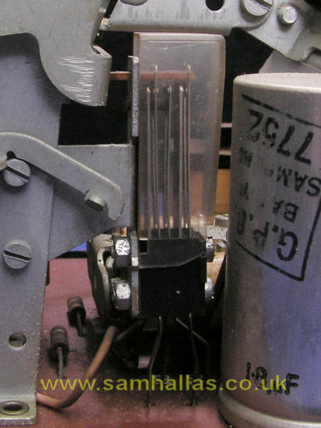
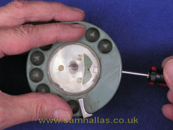
The dial is held in this circular clamp arrangement and on many versions is shrouded with a clear polythene cover to keep out the dust. The red phone had a cover: the green phone did not. The small screw at the front of the dial needs to come right out, but the larger 4BA clamping screw at the back should only need to be loosened sufficiently to allow the clamp to be removed. Once the cover was off I put the small screw back in to avoid losing it. The drying marks round the rim of the red phone's dial lend credence to my belief that the phone had been underwater at some time.
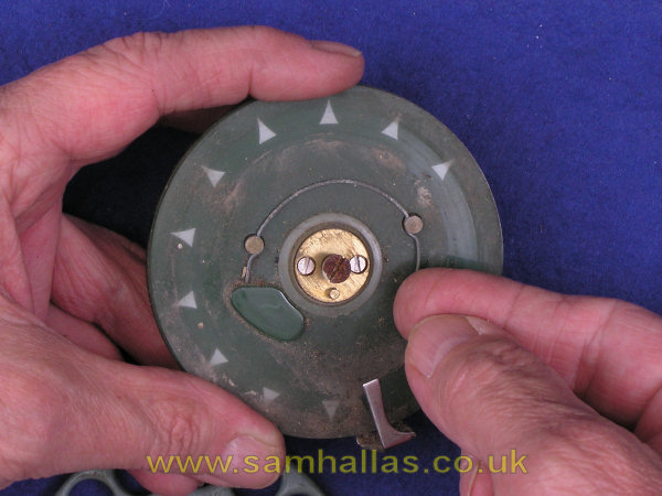
Time to remove the dial cord. To save you writing them down the colours go: Orange, Pink (toward centre), Brown, Slate, Blue. Early telephones 706 were fitted with a Dial No 12 with a metal finger plate, but the two here have a Dial No 21. Both types of dial have the cunning trigger action which you can see by winding the dial up and watching the pulsing mechanism as it dials out. As illustrated on the previous page, later models of Dial No 21 had a clear plastic finger plate - probably polycarbonate - with numbers behind.
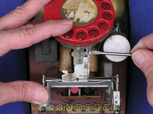
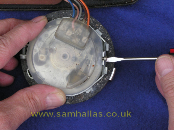
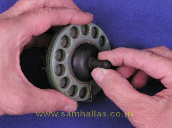
To get the finger plate off, the window must be removed - the Post Office called it a 'label protector'. The window is a push fit into the centre of the dial. On coloured dials the fit is fairly tight so a spring is provided which can push the window out when a small screwdriver is turned against it as shown. I've taken the label out so you can see the spring clearly.
On the clear dials the fit is much slacker and the PO rubber sucker, Extractor No 29 (LH picture below), should be used. Alternatively use a length of sticky tape held in the fingers. Press its centre onto the dial window, then pull evenly. The windows on coloured dials are such a tight fit that it's a real struggle to make the Extractor 29 rubber sucker work. Next, undo the screw in the centre and lift the finger plate clear. Release the spring retaining the number ring and lift it clear.
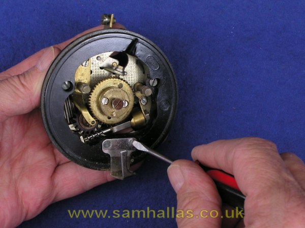
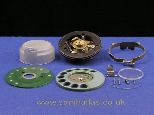
If the finger stop needs to be cleaned you can remove its retaining 8BA screws (Centre picture below) and lift it out. I'm not going to take the dial any further apart. Pictured Right are all the bits from the dial. [Back row: polythene contact cover, main dial mechanism, circular clamp. Front row: inner number ring, finger plate, finger stop, window (label protector), finger stop screws, finger plate screw, support bracket screw, number ring retaining spring]
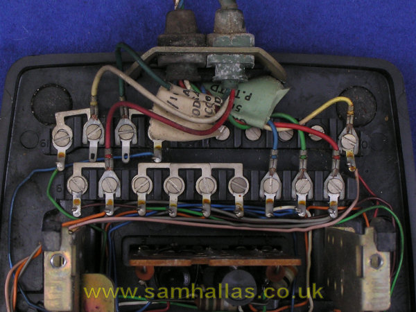
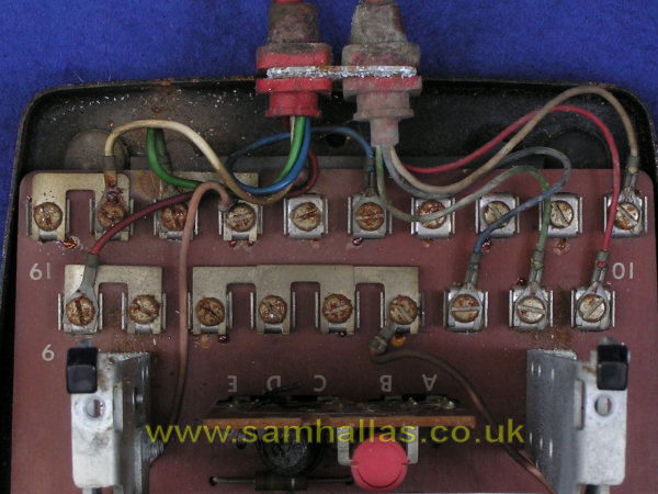
Although the appearance is very different between the two models, the terminal numbering and layout are the same. The wired version has 6BA nuts set into the plastic base with cheese headed machine screws. The printed circuit version uses steel shell inserts with self-tapping screws. The grommet retaining slots are a separate steel pressing on the wired version which pushes into the plastic base. On the printed circuit version the grommet bracket is rivetted to the base.
The desk cord and handset cord can be removed now. The wire colours are shown in the N-Diagram, N806, so no need to write them down.
The sheer number of links between terminals is testimony to the thought that's gone into the circuit design. By rearranging the straps a multiplicity of different circuit types can be catered for: shared service, extensions plans, switchboard extensions, local battery working, and so on.
 Previous
Next
Previous
Next