
Sam Hallas' Website
Click the images for a larger version. Click 'Close' or press ESC to return.
So far all of the systems we have looked at have been synchronous systems. This needs very good speed control at both ends, and some means of correcting any lack of synch.
Around 1906, Jay Morton and Charles Krumm of Chicago started experimenting with machines that worked on what is known as the start-stop principle. It still used a five unit code, like the Baudot and Murray systems, but the transmitters and receivers come to rest when not actually processing a character.
To send a character, first a 'start' element is sent to line. This starts the receiver going. Next come the five code elements, and finally a 'stop' element. The stop element can go on until the start of the next character, but it has to have a minimum length to let the receiver come to a halt. So minor speed differences between ends are automatically put right at the start of each character. This means simpler governors and no need for special synch signals.
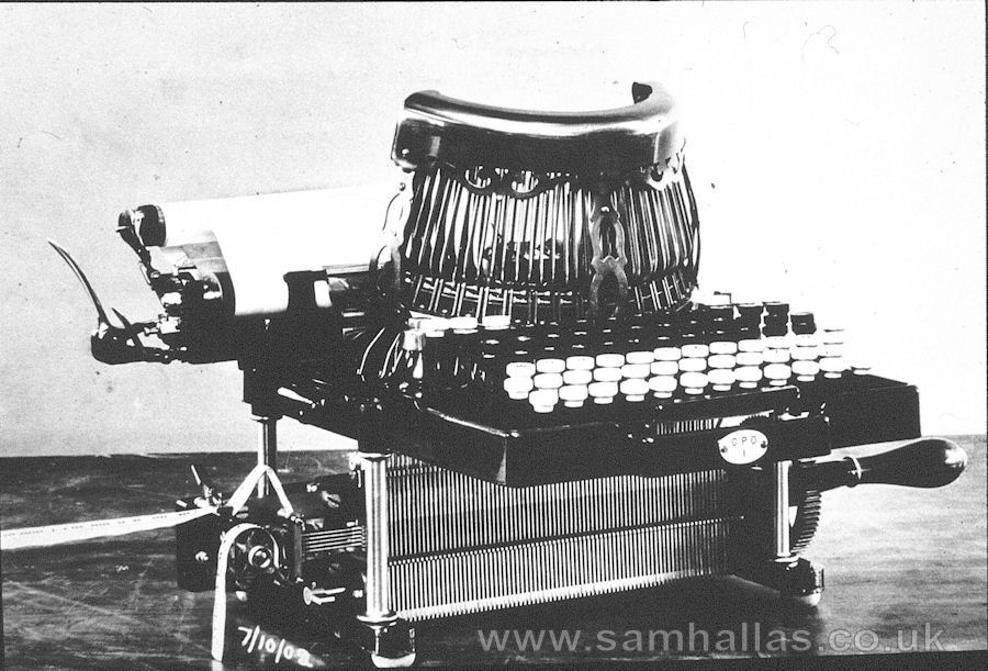
Morton and Krumm formed a company with the totally unmemorable name of Morkrum to make their machine. It started to be used around 1920. However, they chose a better name for the machine: it was called the Teletype. The Teletype printed straight onto paper tape at up to 40 words per minute. (A typical Morkrum page printer from the period is illustrated at the bottom of the previous page.)
Printer No 1
Creed model 3
When these machines started arriving in Britain, Creed lost no time in meeting the challenge with a whole series of machines. Starting with the Model 1P page printer, left [Picture: BT Archive], then the 2P and finally the Model 3 tape printer, Creeds first combined start-stop machine, was introduced in 1927 for the Post office telegram service.
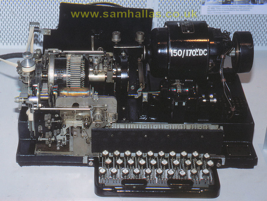
The famous model 7 page printing teleprinter, below, came in 1931 and was used for the inland Telex service. It worked at a speed of 400 characters a minute, about 66 words a minute, using a code based on the Murray code. It was later recognised as International Telegraph Alphabet No 2 - the one still in use today for Telex and RTTY.
Creed model 7
Creed model 444
Trend telex terminal
Over the years, many fine teleprinters, such as the Model 444 illustrated, have been produced by Creed in Britain, Teletype in America, Siemens and Lorenz in Germany and Olivetti in Italy. All of these machines work on similar principles. They have not changed much since the 1930s, except in matters of individual detail.
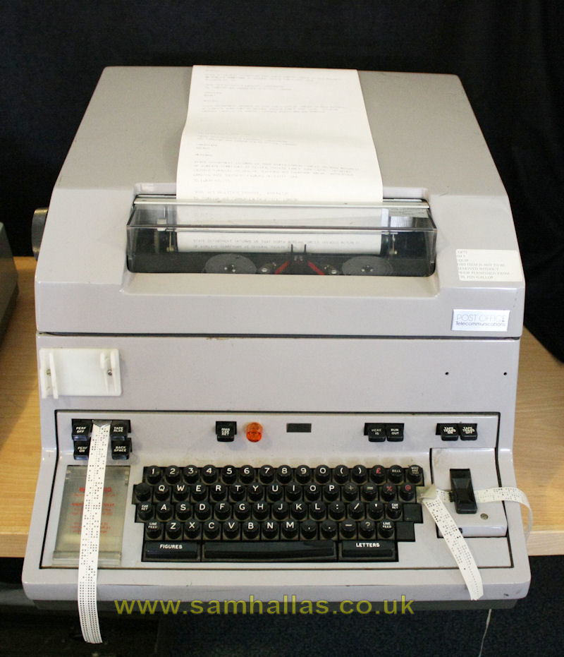
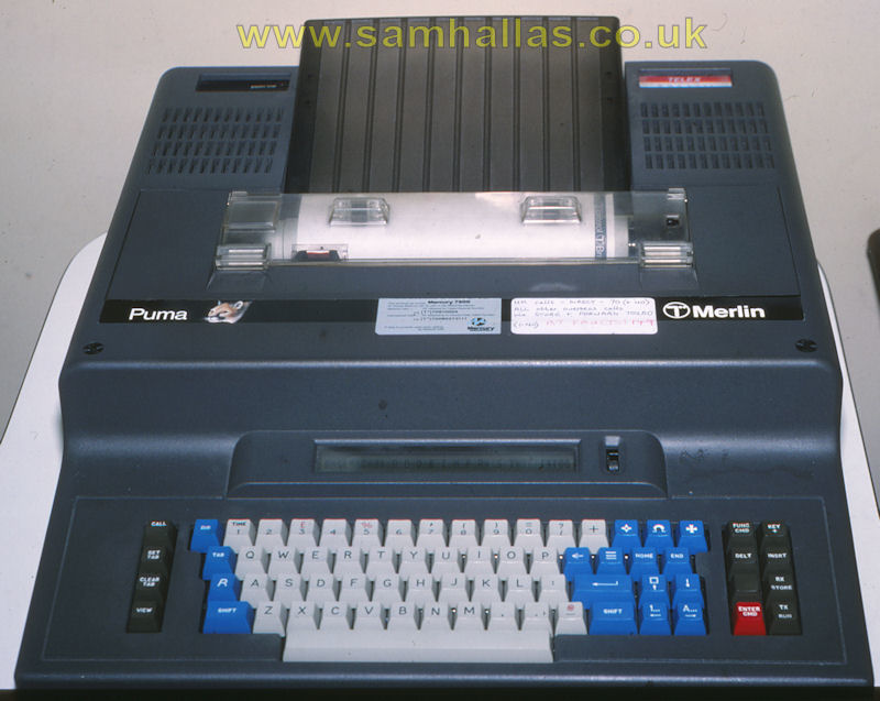
Today [ie 1987], however, most of the machines in commercial service have been replaced by semi-electronic machines. The coding, transmission, reception and decoding are all done by integrated circuits. The only moving parts are the actual print heads. The Trend Telex terminal, right, is a typical example from the period. The Telex service itself is under threat from the widspread use of FAX and electronic mail. BT discontinued the Telex service in the UK in 2008. For an article about the history of Telex see the Light Straw pages
Spark gap transmitter
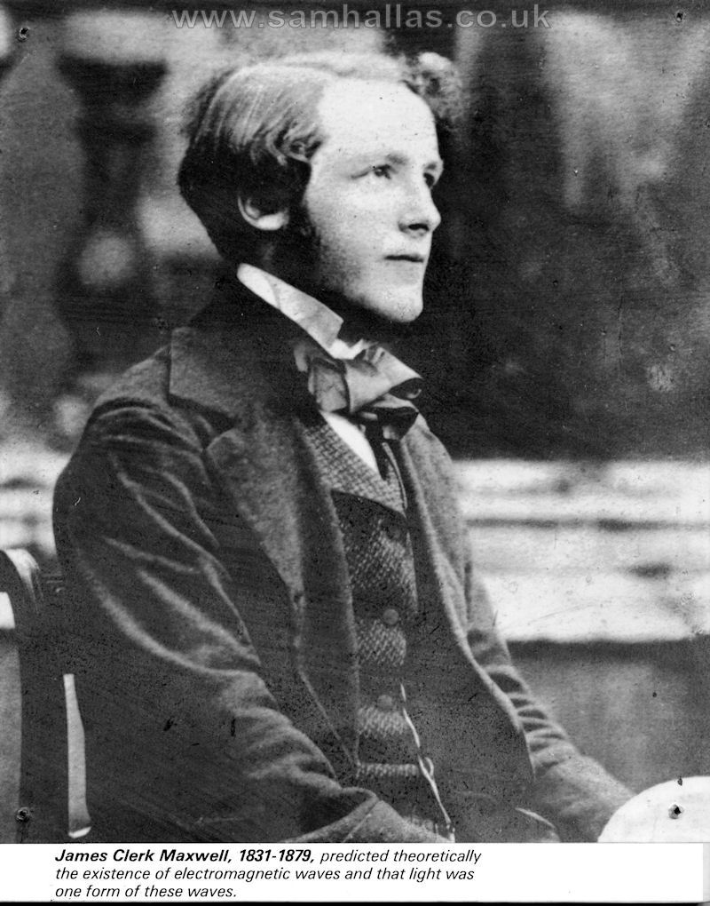
James Clerk Maxwell
Of course, all these early telegraph systems were intended to be used over cable circuits. But at the same time as telegraphs were growing from infancy, radio was also growing up as means of transmission. It all started with the experimental work of Oersted and Hertz. They showed it was possible for the unknown waves to travel without wires. Maxwells theoretical calculations showed how it all worked. [Maxwell picture: Science Museum]
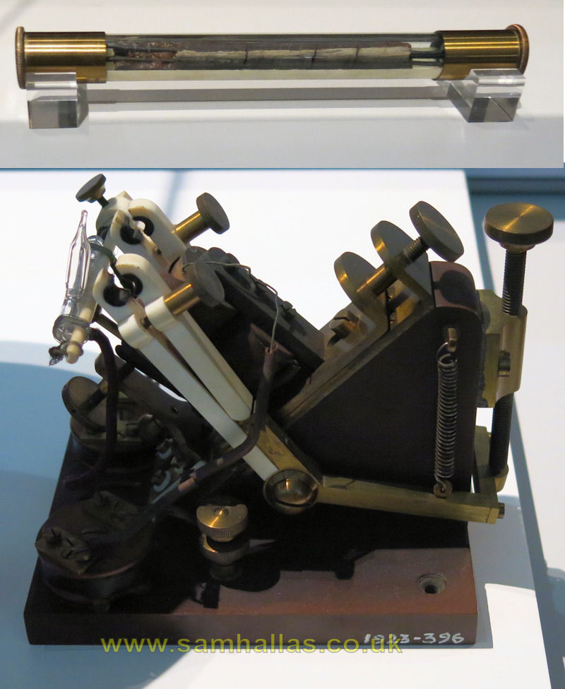
Coherer & tapper
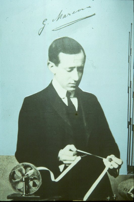
Guglielmo Marconi
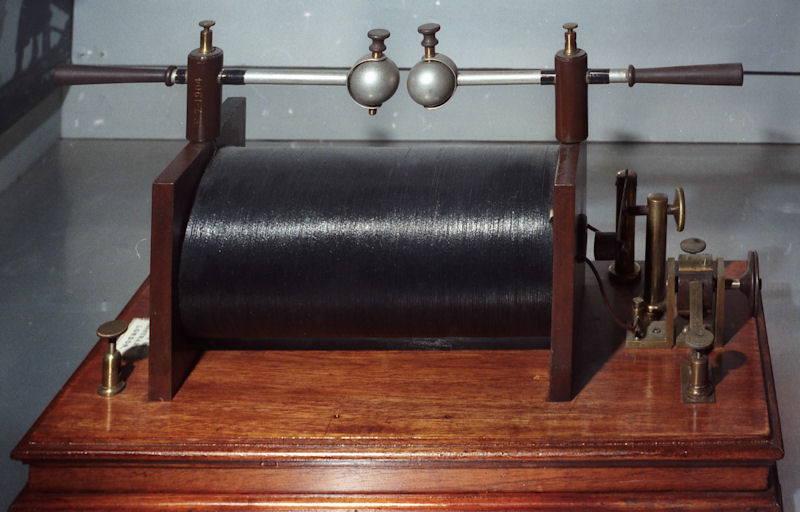
The earliest transmissions used spark gaps to make the radio waves, and magnetic detectors, and coherers to detect them. It led in 1901 to the milestone of Marconis first transatlantic transmission. [Marconi Picture: GEC]
The first transmissions used hand sent Morse code, but so as to get as much traffic over the air waves as they could, the telegraph companies were soon using automatic transmitters and receivers - and later, printing teleprinters.
We have looked at telegraphy, sending letters, character by character, but what about facsimile transmission, or FAX, sending pictures by wire or radio?
Bains recording telegraph
It comes as something of a surprise to find that FAX has a history nearly as long as telegraphs. The first working system was invented by Alexander Bain - who invented the Morse recorder mentioned earlier - as long ago as 1842.
Bain had invented a system of synchronised clocks and he saw that the pendulums, linked together electrically, swung together, reaching the ends of their swings simultaneously. By fitting a contact at one end, moving over letter shaped contacts and a stylus at the other end, he was able to reproduce the patterns of the letters at a distance. The stylus moved over chemical coated paper and the paper was moved forward on each swing, so tracing the shape of the letters.
Its success was limited and in 1850, Frederick Bakewell's invention of a cylinder and screw, rather like the phonograph cylinder, set the pattern for later FAX designs.
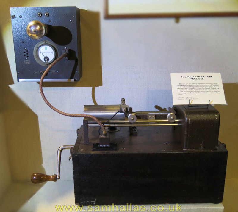
Fultograph picture receiver
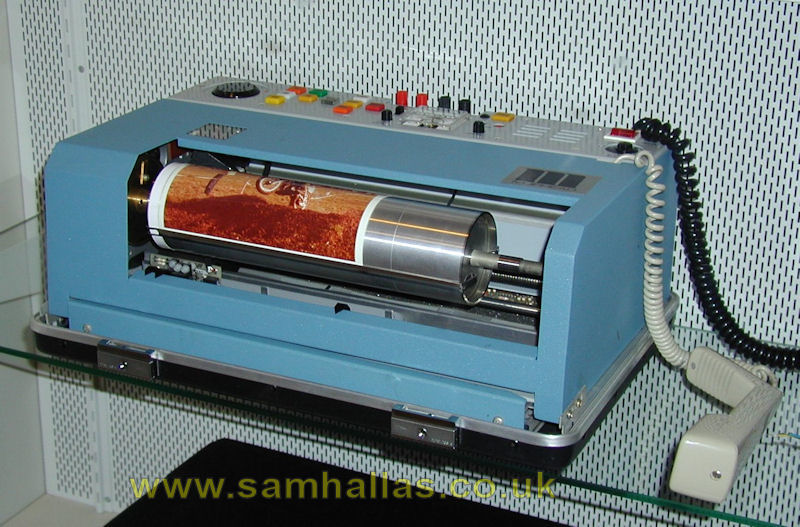
Muirhead colour facsimile
The real advance in FAX was the discovery of the light sensitive properties of selenium. In 1902 Dr Arthur Korn made the first photoelectric FAX for transmitting photographs and in 1921, Edouard Belin used equipment like this to send pictures across the Atlantic. The first radio FAX transmission across the Atlantic took place in 1928.
FAX has moved along with technology, driven by the needs, mainly, of the newspaper business. Improvements such as white space skipping, and run length coding have speeded things up. Even comparatively recently, machines from Muirhead and others still used the basic revolving drum technique, though pictures are now sent in colour - originally by three separate transmissions, later by simultaneous transmission.
FAXs today use raster scanning, like a television picture, and print on heat sensitive paper or use ink-jet or laser-jet technology.
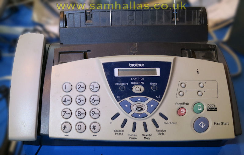
Brother FAX/ Copier Machine
at MK Museum

Dr R.W. Hamming
Anyone who has ever used a radio will know that they suffer from noise. What happens to a data transmission is that the wrong characters are received. Now, with ordinary text, enough is still left for the human brain to make some sense of it. But if there is a mistake in coded text or pure data, of course, there is no way of guessing what the right letters should have been.
Thanks to many mathematicians there are ways of detecting and, if possible, correcting errors. The trick is to send more data than is needed - this is called redundancy. If there is bad reception, then the extra bits help to put the message back together. One of the best known names in this field is R.W. Hamming of Bell Labs who published his paper on error correcting codes as long ago as 1950.Picture: Bell Labs
A fairly simple way of correcting errors was called Telex Over Radio, better known as TOR. This was developed in the early 60s for long haul radio circuits and for sending telex to ships. If the receiver spotted an error it signalled back to the sender and the characters were sent again. The commercial SITOR (Simplex telex over radio) was adapted in the 1980s by Peter Martinez, G3PLX, to make a system for amateur radio teleprinting, called AMTOR.
Nowadays, integrated circuits and microprocessors have made it possible to send data by radio for all sorts of jobs, without the errors caused by poor reception. Here are a few examples.
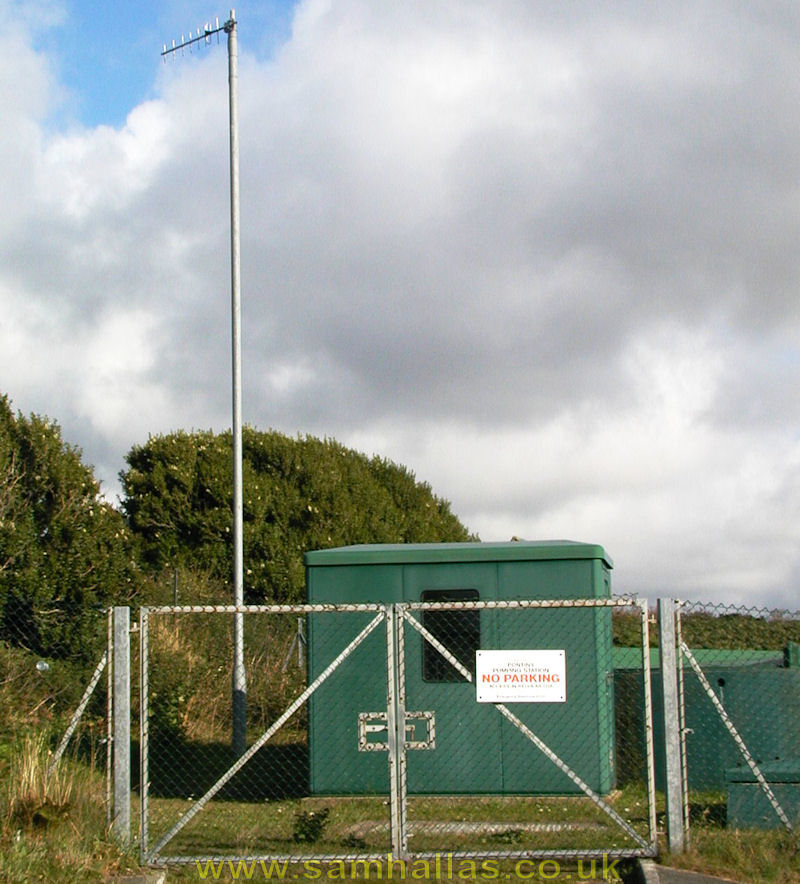
Telemetry at a sewage plant
in Jersey
The public utilities often have plant in the middle of nowhere. Radio telemetry lets them read instruments, and work controls from the comfort of a central control room.
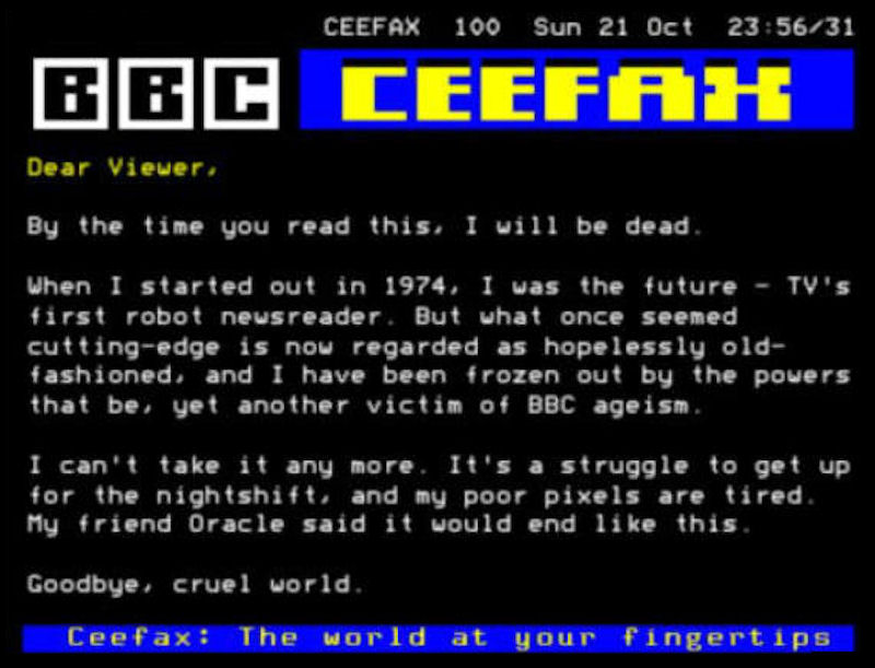
BBC Ceefax
Many people now have a television set with Teletext. The data is coded onto spare lines in the television frame to broadcast an electronic magazine. Launched as Ceefax by the BBC in 1974, the service was the first in the world. It was finally shut down in October 2012 with the end of analogue TV broadcasting in Northern Ireland.
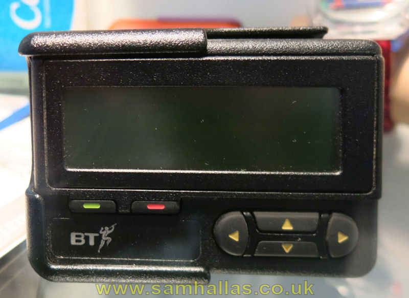
Radio pager
Key personnel who are out of reach of a telephone often carry a pocket pager, or bleep. And again that is just a simple radio data receiver. Picture: PD via Wikimedia Commons
It is now possible to connect portable data terminals, computers, or even FAX machines via the cellular radio network. One can now get straight through to the company's mainframe, wherever one happens to be. Combinations of Forward Error Correction (FEC) and Automatic Repeat Request (ARQ) virtually guarantee an error-free connection. Of course, once the mobile networks went digital, modems were no longer needed and the signalling protocol provided all the error correction.
A good example I can quote is that Network Rail use a secure radio data system to keep the safety of single line working using an electronic token system without the expense of laying cables to the furthest flung parts of the network. Radio Electronic Token Block (RETB) working will eventually be superseded by the European Rail Traffic Management System (ERTMS), but it was still in service in 2014 and expected to last for a good few years afterwards.
We have come a long way from Wheatstone, Baudot, Morse, Creed, and Marconi, but we hope that you will remember when the talk turns to packets and satellites that it all goes back to the pioneers who had the vision of communicating round the world that has put us where we are today.
Many of the vintage instruments used to illustrate the talk were on show at the BT Museum at Blackfriars or at the Science Museum in South Kensington. They are well worth a visit to see them for yourselves. (NB since this was written the BT Museum has closed. See the memorial pages here for a chance to view some of the exhibits. Many are now on display in other museums thanks to BT's former Connected Earth Project. The Science Museum displays were reorganised in 2014 into the 'Information Age' display on the 2nd floor. See the list of exhibits at the end of this article.)
This article is a written version of an illustrated lecture prepared as part of the data communications symposium held during the Radio Society of Great Britain's 50th anniversary in 1987, organised by BARTG.
Thanks are due to many people, especially British Telecom plc for permission to use some of the illustrations. The resources people at the BT Museum were most helpful and advised on the choice of pictures.
Thanks especially to Smudge Lundegard, G3GJW, for his help and encouragement. Unless otherwise acknowledged, the photographs are by Sam Hallas.
In 2014, some 27 years after the original text was written, I thought it was time to review the progress in telegraphy and telecommunications in general in the intervening period.
The result is in the following Supplement, Part 4
These articles copyright 1987-2014, AG Hobbs & SM Hallas.
Back to Top