
Sam Hallas' Website
Index of Files An index of folders with links to the N-Diagrams, Q-Diagrams and TG-Diagrams,
N-Diagrams were used by Post Office technicians when installing or servicing instruments and small systems. The full range of subscriber's apparatus was covered. This is invaluable information for collectors wishing to restore items to working order.
Q-Diagrams relate to the Post Office's House Telephone System.
TG-Diagrams are for Telex equipment and the Telegram service.
SA Diagrams are Subscribers' apparatus, usually reserved for special items.
A list of some popular N-Diagrams can be found here.
Numerical Index An index of N Diagrams in numerical order including the title, PDF Format
Q-Diagram Index An index of Q-Diagrams in numerical order
TG-Diagram Index An index of TG-Diagrams in numerical order
N-diagrams must have been in use from a very early date in the 20th century, but they appear to have been regularised in 1917. The very early ones had a diagram on the front face and a typed description on the reverse. Later ones were entirely hand-lettered. First editions had no revision letter: subsequent editions had revision A, B, C, and so on marked in a box on the LH edge of the first sheet.
All of the diagrams are in Adobe Acrobat® Portable Document Format (PDF). To download the free reader go to the Acrobat Web site
The N diagrams are, strictly speaking, Crown Copyright. However, British Telecom, as custodians of the GPO heritage, state that they may be used for private study and personal use, but must not be copied for commercial gain. Please respect this or it may be necessary to withdraw their availability.
Originally, I scanned only the diagrams in my collection that struck me as being useful to collectors. Due to considerations of space I confined the original batch of diagrams to these. However I have now scanned all of the diagrams in my collection and supplemented the files with scans from kind donors. The Numerical Index lists all the diagrams. I have added to the index all the diagrams in the Telecomms Heritage collection which are highlighted in green in the numerical index. In some cases there is no known copy of a diagram so its content has been inferred from other sources, such as the 'Connections of Telephonic Apparatus and Circuits' published by the GPO in 1909 and known simply as The Red Book.
If you have an N-diagram in your collection that I haven't got, I would be very grateful for a scanned copy, photocopy or loan of it to help complete the collection.
The following are broad guides to the content of the various ranges of numbers. Itis not comprehensive and there are odd quirky items in the middle of ranges.
N001 is an Alphabetical List of Diagrams for Subscriber's Apparatus. N002 a list of PABX diagrams, N003 a list of PMBX diagrams N005 is a list of Bell sets.
Telephones are described on the N-diagram 100 greater than the number of the telephone. Eg Telephone No 706 is described in N806. Hence the series N100 to N499 covers telephones. Bell sets are described in N-diagram 500 greater than the Bell Set number. Eg Bell set No 26 is described in N526. Also in the 500 series are a number of dials. The 600 series contains power units and rectifier with no clear linkage to the type number. The 700 series is mostly concerned with switchboard termination. The 800 and 900 series are telephones once again.
The 1000 series contains diagrams for various subscriber's extension plans.
The 2000 series contains switchboard connections, autosenders, call office circuits, and some plan diagrams. Quite a mish-mash really.
The 3000 series are mostly concerned with shared service working.
The call office theme is continued in the 4000s up to the 4200s. There is more plan working in the 4300s. The 4400s have some curiousities and a number of amplified telephones. More plan working and call offices in the 4600s. The 4900 series is for the Special Range of Telephones.
The 5000 series includes some subscriber's carrier equipment and the 8000 series completes the set with the newer plug-ended telephones.
Some telephones have a diagram in the SA series, such as the early push-button 700 series using Code-C signalling, SA 4252. Paul Ebling explains the difference from N-diagrams.
"SA stands for 'Subscribers’ Apparatus'. They were developed by Telecomms Headquarters S Branch (Subscribers’ Branch) which later became Telecoms Development TD 7 and the were drawn by a Drawing Office in S Branch. The SA diagrams were originally intended for purchasing – so would give the values of every component – or refer out to an S Specification. The SA diagram would probably refer to the Main assembly drawing – or the S Spec would. The main circuit diagram is of interest to field engineers, but they don’t want all the straps in the position when manufactured, they want all the options to do Shared Service, PBX Recall (earth or C wire), Main of Plan 105 /107 or five lines on a 710 (Plan 2) etc. These requirements were specified on the N diagrams, which was focussed on the things the field staff could alter, or change when faulty. Think of the confusion for the manufacturer of say a Key & Lamp Unit if there were 30 or more strap re-arrangements on the SA diagram… Which one is wanted when supplied to stock?
"SA diagrams were allocated to groups, so SA 8XXX would be PABX related – SA8001 – 49 = PABX 1 & 2, SA 8100 – 8254 PABX 3, SA 84XX PABX 4 (BT Version) and so on. PMBXs were SA 7XXX, SA 4XXX were small amplifiers for use in customer premises etc. Some specialised telephones went into there too.
"SA diagrams were THQ originated and used for Contracts but sometimes they were available to the field staff – e.g. the Code C signalling telephone mentioned earlier, SA 4252. Time was too short to develop an N diagram, so a fitter took the SA diagram for the keypad etc and the N846 for the standard bits of telephone circuitry. Not the most efficient, but it reduced launch times for such novel items. The London Telecomms Region had their own series of 'Non-Standard' diagrams."
I have only placed the latest available revision on the web site. Sometimes I have earlier revisions which may be of historical interest. Ask me if you need something. The Telecomms Heritage Group collection includes many previous issues of the diagrams. A list is available to members.
The diagrams were supplied by the Post Office to the British Railways Board, who ran their own internal telephone system. With the liberalisation of customer premises equipment most of the old Post Office equipment became obsolescent and production of N-Diagrams stopped. As a space saving exercise the collection was about to be consigned to the waste bin and so I rescued it.
Fellow THG member Laurence Rudolf has kindly scanned a large number of early N-diagrams in his collection. Thanks, Laurence.
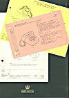
The later ones were in a 1930s GPO folder with George VI crown. The collection includes some diagrams in several different revisions which have been included for completeness and historical interest. Quite a few are very early diagrams, pre-1917, some are undated, most of which came from a small bound book the same size as an N-Diagram. The Red book has the Lion & Unicorn emblem on the cover and the book is titled "Telephone Diagrams". The first page. "For Official use, Post office Telegraphs. Connections of Telephonic Apparatus and Circuits. General Post Office 1909.Price One Shilling and Threepence." This was the fore runner to N-Diagrams. It turns up for sale from time to time at THG swapmeets.
Another THG member, David Roberts, G7MYM, has helped considerably by scanning part of his collection for us. The diagrams relating to plan working in the 4500 and 4600 range are thanks to David, as are the subscriber carrier diagrams in the 5000 series. David has also done most of the work on the numerical listing for which I am very grateful.
I also gratefully acknowledge additional contributions from Peter Duffield and Andrew Emmerson, Kevin Dodman, Jim Foster, David Higgs and the late Ron Sewell and John Goldfinch. Thanks also to Andy Banthorpe, who lent a large number of diagrams including many TG-Diagrams, and to Paul Mark whose collection includes some very early diagrams.
I have scanned these diagrams at 300 dots per inch and stored them in Adobe Acrobat® Portable Document Format. They are reproduced actual size - which varies according to age. The older diagrams are about 179 x 108 mm and the later ones are either A5 (149 x 210 mm) or A4 (210 x 297 mm). They were printed on fairly cheap paper, some pink, some yellow and mostly white (well fairly white). The printing was presumably offset litho and the ink wasn't very black on some of them. The printing is not always straight on the page (honest, I DID put them squarely on the scanner). Later scans I have straightened using my photo-editing software.
The task of indexing all of them has been formiddable. So please excuse the fact that you get an automatically generated list of the files, but it does mean it is as up-to-date as it can be. Use the link below. to access it.
N-diagrams Files Index of folders and links to the actual N-Diagrams
The Numerical Index has been updated to include all diagrams in my collection, with highlights of the ones which have not been scanned yet and those that are known to exist but not presently available. However, there are also links to the relevant diagrams from the pages on Bob Freshwater's Telephone Files site.
[Sam Hallas, updated April 2011 and again Feb 2018. Links to index.php removed Aug 2022]
Document Repository