
Sam Hallas' Website
The single needle was the mainstay of railway telegraphy for many years. Indeed they were still in service in the 1970's on the Great Northern Line out of Kings Cross. The signallers were paid an extra allowance for knowing the needle code and were somewhat put out by the modernisation of the signalling along the line which did away with the telegraph - and most of the signalboxes as well.
The instruments were connected in series on an omnibus circuit, meaning that all the signalboxes on the line could hear the messages in progress. The signallers used to use it in quiet moments for passing gossip along the line. As it was an audible system, they could listen in on the chat on the line whilst performing their normal duties.
For the technical description I am indebted to Railway Signalling and Communications by Tattersall et al, published by the St Margaret's Technical Press sometime in the 1930's to judge from the illustrations. This book is based on lectures given at training schools for the London and North Eastern Railway's Signal and Telegraph Department. Although some of the illustrations now look quaint and the telecommunications sections have been overtaken by digital technology, all the electrical theory and much of the signals practice remain relevant into the 21st century. Indeed it has been a standard textbook for the S&T Department for many years. Extracts can be seen on the Document Repository page.
The transmitter part of the single needle telegraph consists of a commutator operated by a shaft turned by a drop handle, which protrudes from the front of the instrument. As can be seen from the diagram, the commutator is placed in series with the line and the receiver and when at rest presents a short circuit, allowing signal to be received and passed on to other stations. When the drop handle is turned, the short circuit is removed and the battery connected to terminals Y and Z is connected in series with the line. The polarity of the battery is determined by which way the handle has been turned.
By turning the handle to one side or the other and back to the centre again a series of pulses of current of varying polarity are sent to the line. Notice that the receiver is connected in series so that the operator has visual and audible feedback of the code being sent.
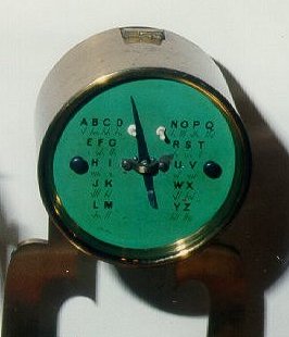
The receiver has an indicating needle on the faceplate which travels between two stops, which are designed to emit different notes when the needle hits them. The shaft holding the needle supports an armature which swings between two coils. The shaft and armature are split in the centre by a non-magnetic divider and a pair of horseshoe magnets polarise the armature as shown in the diagram. This method of operation is known as Spagnoletti's induced needle (or axle), named in 1869 after the famous Railway Telegraph Superintendent, Charles Ernest Spagnoletti (1832-1915).
A current in the coils causes the needle to rotate. A positive current causes rotation in one direction, whilst a negative current causes rotation in the other direction.
A number of instruments may be connected in series along a section of railway, as shown in the diagram. The end points are earthed and the commutators at rest provide a continuous circuit. Operating the transmit commutator at any intermediate point places the battery in circuit, as on the right-hand side of the diagram. There are batteries at each of the other two sites, but they are omitted from the diagram for clarity.
The code is shown in the diagram below. Note that it is also marked on the face plate of the instrument illustrated at the top of the page. It can be easily seen that this code is identical to Morse code: a LH deflection being equivalent to a dot and a RH deflection being equivalent to a dash. However, the lengths of the code elements can be identical, since they are distinguished by the direction of deflection together with the different tones emitted by the needle stops.
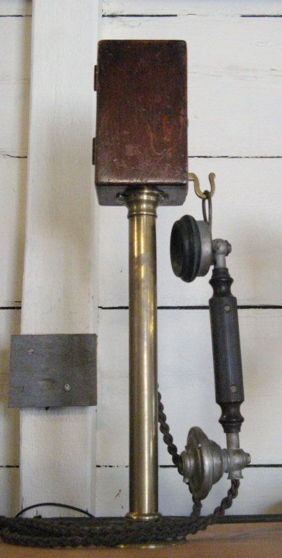
While we're on the subject of raiwlay telegraphs, here's an interesting application. It is normal practice to provide a bell signalling circuit between signalboxes for block section train working. By a simple modification a telephone circuit can be superimposed on the same single-wire bell circuit to allow speech.
The block telephone illustrated on the right is one of several on display at the St Albans South Signalbox museum.
A very basic local battery telephone circuit with an induction coil for the transmitter circuit is connected between the bell line and earth via a capacitor to block the dc bell current. A refinement in this diagram, not always applied in practice, are the chokes in series with the line, presumably to suppress clicks from the bell interfering with speech. The blocks with serrated edges are lightning arrestors in the pictorial style of diagrams at the time. No calling indication is needed as the signaller would send a bell code meaning 'come to the telephone'.
The block telephone is a later simplification of the Phonopore, an invention that saved the railways a lot of money.
Next: The GWR Selective System as used on God's Wonderful Railway
Photo & text, © 2000-2008, Sam Hallas, unless otherwise credited
Reference: Railway Signalling and Communications, Tattersall et al,
St Margaret's Technical Press, 193?.