
Sam Hallas' Website
by Mike Tyrrell

In 1963 as the modernisation of the Southern Regions Telecommunications network gained momentum, the demand for automatic telephones, and the consequent reduction of switchboard operating staff, went beyond the reach of the new cables then being laid at the trackside on the year- by- year 'cabling of aerial wires' rolling programme.[picture of aerial wires: Roger Carvell]
New PABX systems were being installed at main centres and larger stations but their reach was limited by the lack of line plant away from the locality of the station. Communication with the more distant locations was by the use of battery ringing omnibus circuits which require manual set up and supervision.

The problem was how to reuse the line wires of the existing omnibus telephone circuits for user-dialled calls. The length of the lines and number of telephones over the route caused implementation problems. The solution was to use a system designed for lines longer than the ruling 750 or 1000 ohm loop and suitable for more than the two telephones possible with conventional party line working. [Picture of omnibus phone: GEC]
Siemens-AEI Woolwich had produced a RURAL PARTY LINE system for use in a mid-African country to allow access to a number of telephones on a single line over dispersed rural areas. The system comprised a short, free-standing rack mounting 2000 type relay sets: each rack potentially capable of controlling 9 lines; each line capable of accommodating twelve telephones. Line signalling was conventional loop disconnect pulses inward, and 25 Hz 75Volt ringing current outwards to the line. However the line voltage was increased from its normal 48 volts to extend the reach of the line in service. One of the units originally designed for export was put into service for a trial between Ashford and Tonbridge and found to work effectively over the existing line plant.
On receipt of the dialled number the control unit selected the required line and transmitted selection signals to line. The required telephone was selected through the operation of small relay unit installed at each telephone position. A short high voltage pulse was sent to line to operate a polarised relay at the telephone selected, allowing the bell to be rung from conventional ringing current. All the other telephones connected to the line remained disconnected. Only the required telephone rang and the rest remained silent. The main drawback of the system was the numbering scheme. It was a freestanding exchange unit with dialling junctions to its parent exchange. The numbering scheme was three digits, the first digit selecting one of the maximum of nine lines, the second and third digits one of the twelve possible telephones connected. Twelve was selected based on the maximum possible combinations of selecting signal not numbering scheme considerations. In the incoming direction the dialled pulses from a standard dial were passed to the parent exchange via the connecting junctions after the user dialled the digit 0. Direct telephone-to-telephone operation was by simply dialling the three-digit number.
Despite these drawbacks the system functioned as a multi-party line system. Individual telephones could be called directly from the network without the aid of an operator. Telephone users could dial direct to the network. Calls to other telephones on the same line would encounter busy, as in normal circumstances, but after dialling the user would release from the call to wait for the ringing to the other party called to cease. A capacitor in the receiver circuit allowed the user to listen in to the ringing as ringing tone.

Following successful trials with the export unit, the decision was taken to specify a new unit based on the line signalling principals of the trial unit, but with improved numbering performance. The Southern Region had by this time standardised on the BPO PABX 3 for its telephone switching system. This was to form the basis for the new system. The Southern Regions numbering plan was at this time standardised into a 2 + 4 format, with a two-digit zone code and a fixed format four-digit number.
The equipment was to be installed in the same location as the parent exchange so power, ringing, pulses and other common services would be available on site. Standard PABX 3 racks would be used for mounting 2000 style equipment. Two versions were specified, a 10-way rack and a 5 way, each having the full functions of a Line and Final Rack within the PABX 3. The standardisation of the circuits to the PABX 3 system enabled the racks to be installed who ever manufactured the parent exchange equipment. [Picture of PABX 3 line & final rack: Sam Hallas]
The numbering scheme would follow the standard four digit local numbering scheme of the parent exchange, generally digit 7 was spare at most sites, so standardisation of design could be achieved. The only concession needed was on calls from phone to phone on the same line, where the line had to be released to allow the call to be completed.
After a protracted negotiation, a contract was let to Siemens-AEI Telecommunications Private Systems Division at Sydenham for the first five units.

A standard line circuit was backed by 50-volt positive battery and a high quality transmission circuit to extend the line limits by sending 100 volts to line.
Line selection was achieved by the use of two coded 130-volt pulses. By using a signalling earth return, coding each pulse either negative or positive and using each leg of the line separately, a total of 10 independent selections could be made. The cold cathode tube has the property of striking to a high voltage pulse then holding to a steady state and not passing current in a quiescent state below the striking voltage. The first 130-volt pulse operated some of the polarised relays, which held to the steady state current on the line. The second 130-volt pulse would only operate one of the second polarised relays held operated. Thus each of the ten telephones on the line could be separately rung. [See the Circuit Diagram and strapping chart] [Picture of cold cathode tubes: Mike Tyrrell]

The 10-way control rack was a standard 7ft 6in by 4ft 6in PABX 3 rack in light straw finish. The rack operated as a full 1000-line group within the exchange. The first digit dialled on an incoming call routed the call to the local second selectors. The second digit routed the call to the party line rack on a normal within exchange 4-wire trunk so no relay sets were needed at this point. The third digit selected the line required and the fourth digit determined the selection code to be sent to line. [rack picture Railway Gazette in Andy Emmerson's collection]
Calls outgoing from the selective line were stored in the line control relay set, as second digit discrimination was needed before the routing decision could be made, so no First Selectors were needed.

Adjacent to each telephone a small wooden box contained two cold cathode tubes, each wired via a strapping block to a rectifier and a relay. Thus any unit could be strapped to accept any of the ten selecting codes. When the code was set, the first pulse would operate the first relay, then the second pulse would operate the second relay which would hold to the voltage on the line. The first relay would release so that when ringing was applied to the line the bell in the telephone rang, All the power needed at the telephone was line fed so the installation and maintenance of the telephone and its relay box was a simple matter. [Picture of selector box: Mike Tyrrell]
The selector box was wired to a standard 710-type telephone. Two buttons were fitted, engraved "A" and "B". Operation of the A button looped the line and allowed dial tone to be heard for the call to proceed. The B button released the A button to allow the user to listen to the ringing on the line as ringing tone on own-line calls so that, as far as possible, the operating procedure was kept standard. A standard PABX 3 pip-pip intrusion tone was returned to the caller on own line calls to indicate that the B button should be operated. Outgoing calls from the telephone transmitted standard loop disconnect dial pulses to line to route the call.
The user lifted the handset, listened to ascertain that the line was free, then pressed button A to loop the line, which caused dial tone to be sent to line. On network calls the user received Ring Tone / Busy Tone / Number Unobtainable Tone in the usual way. On "own line" calls however the caller received Warn Tone, which was a signal to press the B button, which released the A button allowing Ringing Signal to be heard, via a capacitor, as a crude Ring Tone. The called party could be heard answering, at which point the caller would press the A button once more to complete the call.
Thus now rural locations off the modern cable infrastructure could now have direct dial access to and from the emerging national telephone network and operating staff could be released from more and more locations. Eventually the Southern Region had only one switchboard at Waterloo.
As the programme of conversion continued, the supplier, Siemens-AEI was taken over by GEC, so the second and final order was completed at the GEC Ford Street, Coventry factory. A total of 13 or 14 sites were eventually equipped with systems so there must have been between 500 and 600 telephones in use at its peak use.
The auto party line system fulfilled a need at the time that the network was growing. As the main network extended, so did the use of the telephone. Ten busy telephones sharing one line was not acceptable. An emergency call on a busy line needed cooperation of others to clear the line as no priority could be provided.
Long open wire lines and the 100 volt standing on the line increased the fault rate and with the march of time, new exchanges, new lineside cables and transmission systems connected to the new national network gradually replaced the system with direct extensions but the original introduction of the automatic party line system allowed modernisation to get under way.
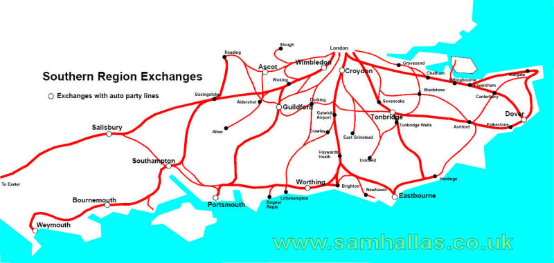
DETAILS of SITES EQUIPPED as at Mid-1984.
|
Site Name |
Lines Equipped |
Numbering Plan |
Approx Date |
|
ASCOT |
3 |
7700-7729 |
1974 |
|
BOURNMOUTH |
8 |
3700-3779 |
1967 |
|
CROYDON |
10 |
7700-7799 |
1978 |
|
DOVER |
5 |
3700-3749 |
1967 |
|
EASTBOURNE |
10 |
7700-7799 |
1969 |
|
GUILDFORD |
10 |
8700-8799 |
1967 |
|
PORTSMOUTH |
5 |
8700-8749 |
1964 |
|
SALISBURY |
10 |
3700-3799 |
1974 |
|
SOUTHAMPTON |
10 |
2700-2799 |
1976 |
|
TONBRIDGE |
10 |
7500-7599 |
1975 |
|
WEYMOUTH |
5 |
4710-4759 |
1974 |
|
WIMBLEDON |
10 |
8700-8799 |
1970 |
|
WORTHING |
10 |
8700-8799 |
1971 |
Sam writes: Andy Emmerson tells me that a number of auto party line telephones and selector cabinets survive in private collections. I'd like to photograph them if possible. Also if anybody has items for disposal please get in touch with Andy via me.
See the article from the Railway Gazette for May 1963 in the Document Repository for information on other means of providing service to telephones on low-density lines.
Text © 1998/ 2008 Mike Tyrrell, revised and illustrated version of an article that appeared in the Telecom Heritage Journal Issue 31. Map © 2008 Sam Hallas. Pictures as attributed. Circuit diagram redrawn SMH. Thanks to Andy Emmerson for additional information.