
Sam Hallas' Website
The first in a series of articles where I dismantle a telephone to show its construction and pass my own opinionated comments on the design and choice of material.
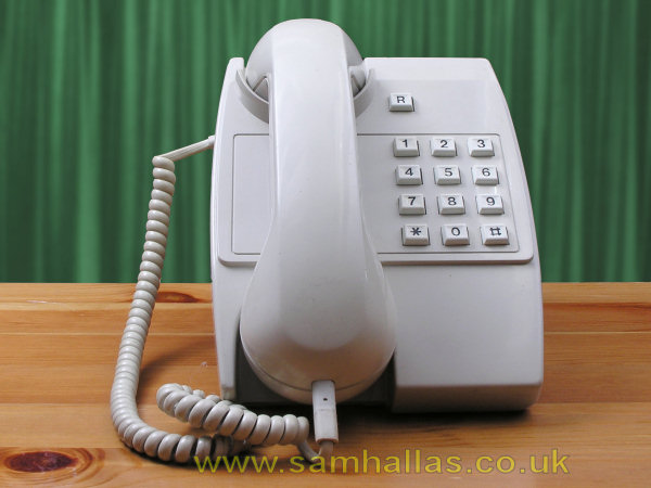
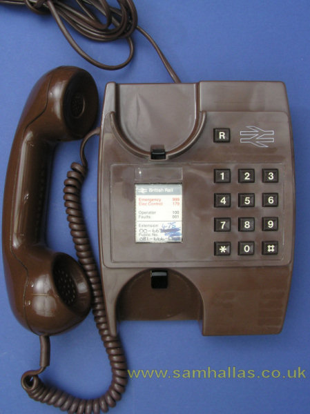
The Statesman telephone looks like this. The The one we're going to take apart is one supplied to the British Railways Board and so is embellished with the BR logo. The other difference on BR models was the fitting of a Bell 84 instead of a tone caller. As we shall see this telephone has been rebuilt to the normal standard with a tone caller.
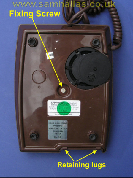
Heres a view of the underside. The lid is held on by the M4 fixing screw. This is the only screw in the entire case. Models built after about 1985 have the two retaining lugs at the front. The case stays together without the lugs, but someone obviously thought they were needed. The lugs on their own are actually sufficient to hold the case together without the screw.
By levering GENTLY with a screwdriver blade the base can be lifted from the cover. The base should lift clear since the tone caller is connected by the spring terminals visible in the picture below. There are no flying leads.
Now is a good time to examine how cleverly the case is designed.
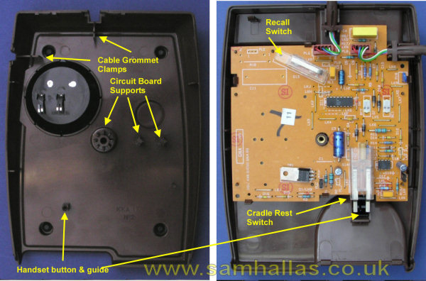
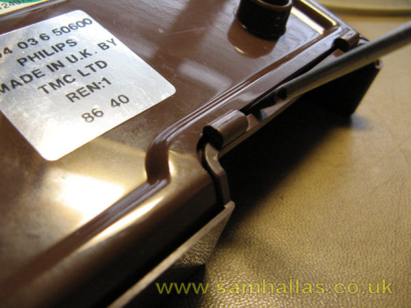
Note the way the line cord and handset cord grommets fit into the case mouldings. When the cover is in place the cords are firmly clamped. There is a guide to keep the handset button straight as it goes up and down. The central pillar where the screw fits is expanded with fingers to hold the circuit board firmly in place. Similarly there are pillars to provide support under the keypad to stop the board flexing when buttons are pressed.
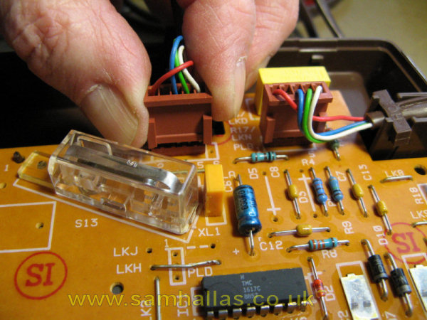
There are no permanent connections to the circuit board. The tone caller has spring contacts as shown on the right in the picture above. The line cord and handset are on polarised connectors which unplug easily. Wiggling the connectors helps to release them (upper left).
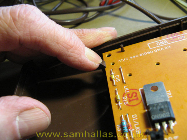
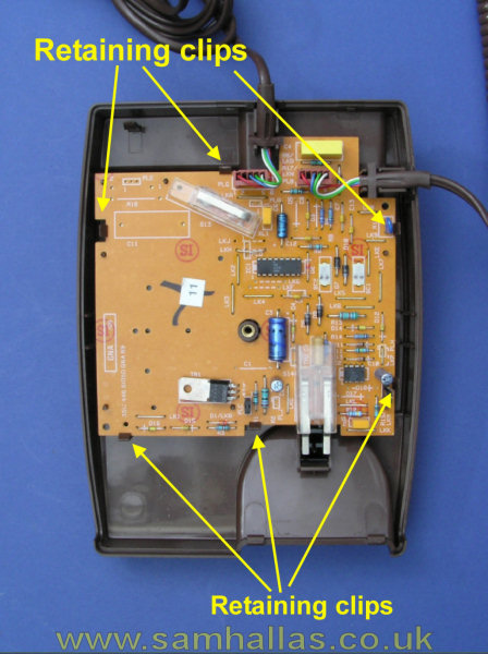
The circuit board is only held in place by retaining clips in the cover moulding, making assembly very quick and easy. The board can be unclipped by pulling the clips away from the board and applying upward pressure to the board. (lower left) I usually start at one end and work towards the other.
