
Sam Hallas' Website
The second in a series of articles where I dismantle a telephone to show its construction and pass my own opinionated comments on the design and choice of material.
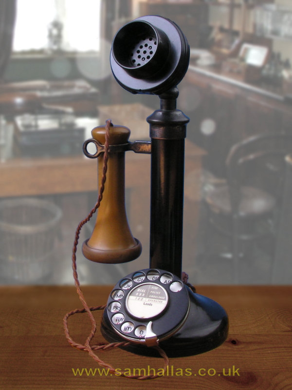
The pillar style of telephone, better known as the candlestick, appeared in the 1890s. The design was smaller and neater than other contemporary designs, which usually had a large wooden box, usually fixed on a wall, containing the bell, magneto and induction coil.
The convenience of the candlestick was achieved by separating the transmitter, receiver and switchhook from the remainder of the parts which could be mounted out of the way in a wooden box, or Bell Set. Even though telephones with handsets became available about the same time, they remained bulky and heavy. The candlestick remained popular for many years because it could easily be carried about the room.
What we have here is a British Post Office Telephone No 150, introduced in 1924 as a BPO standard design. Like many, this one was remanufactured from an earlier Telephone No 2. Its dated 1928. Before we take it apart, lets have a look at its construction and materials.
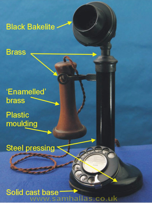
The telephone stands on a cast steel base plate. A good choice of material, adding weight to give stability. The base accounts for a good deal of the surprising weight of the whole telephone. Originally it would have been fitted with a hard rubber ring to protect surfaces from scratching. As rubber deteriorates with age I presume that any ring this one had has long since perished and fallen off.
The curved base and tubular shaft are two steel pressings. The shaft screws onto the base. The steel gives structural rigidity without raising the centre of gravity, preventing toppling. The black finish is stove enamelled. The switchhook fork is brass with a black oxidised finished. It is made from two pieces of strip joined at the body and spread at the far end. I cant see any benefit here of using brass instead of steel, except that it allows the decorative finish. The machining involved is minimal.
The shaft cap and transmitter support are a single brass piece, turned and machined to shape. The superiority of brass at machining means that its an obvious choice. The transmitter is hinged using a separate brass piece not visible on this picture. The transmitter housing is black bakelite the wonder material of the age durable, heat and chemical resistant, with high electrical insulation. The receiver cap is in brown plastic, probably a version of Ebonite, but the housing is brass with a brown coating, described as enamelled.
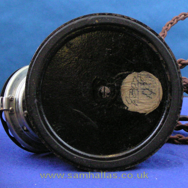
A single captive screw holds the base plate. Once removed the routing of the cords is evident. The transmitter housing and internal chassis are now loose so you should not let them fall out yet.
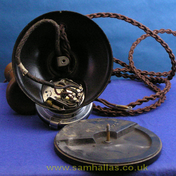
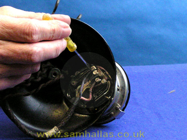
To allow removal of the internal chassis the dial cord must be disconnected. Note the wire colours before you start. They dont always match those in the N-diagram.
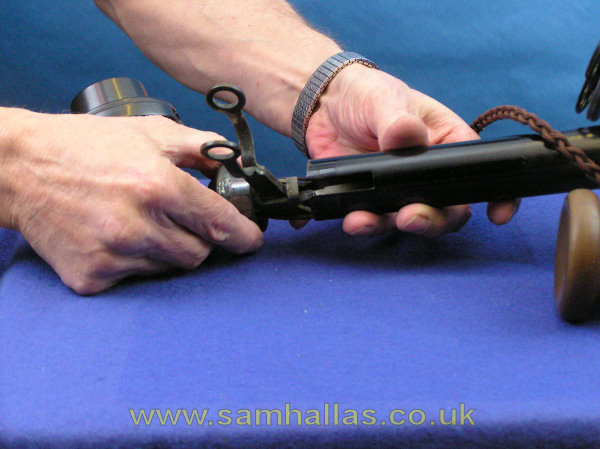
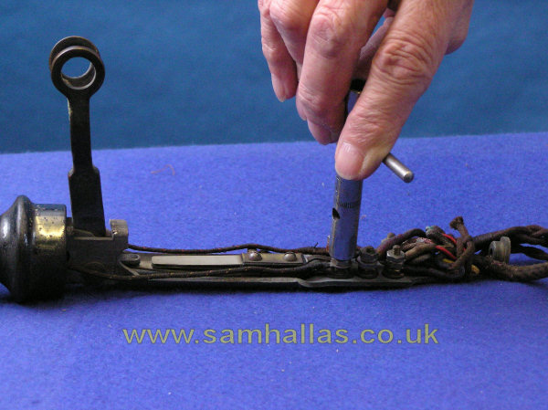
Push plenty of slack in the desk and receiver cord through the grommet in the base and slide the internal chassis and transmitter housing out.
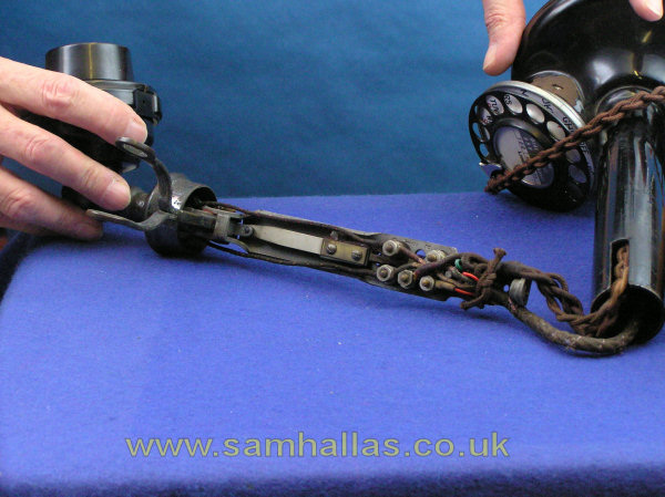
The terminal block is a rats nest of wires and in my opinion is a weak point in the design. The desk cord has a lashing loop at its end which ties it and the receiver cord to the chassis. Both these cords have been replaced and you can see now that although the receiver cord is braided cotton outside, its newer PVC inside.
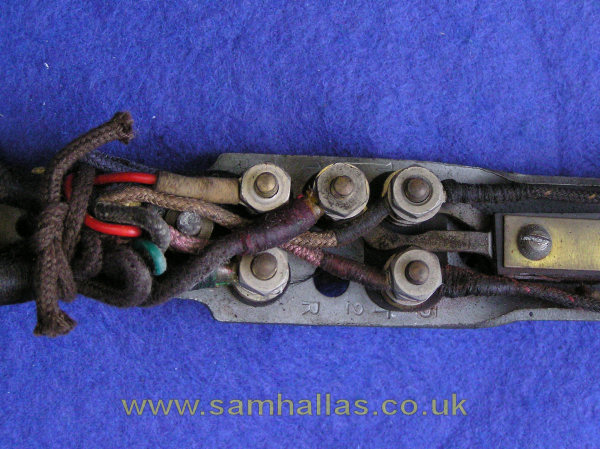
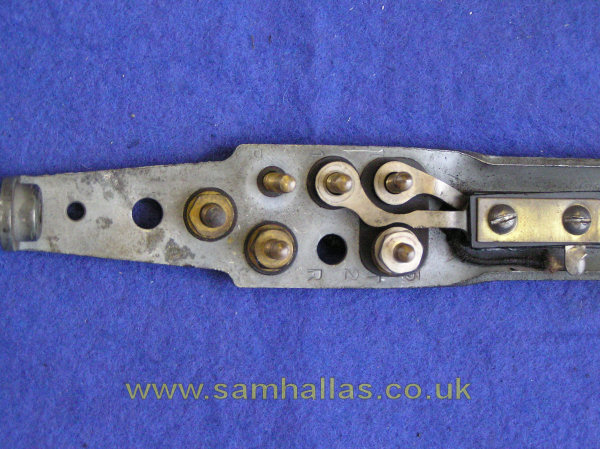
Before we proceed further with dismantling the phone we need to disconnect the various cords after untying the lashing loop. Again make a note of the colours just in case. Typical Post Office! The nuts are 3 BA (and the threads it appears). I used a box spanner to loosen them. Washers tend to get lost over time and I thought there were a few short. 4BA washers from the sparesbox fitted fine.
The way the terminals are constructed is quite cunning. It avoids the need for a separate insulating support for the screws. Each hole is over-size and fitted with a fibre collar. The screws have fibre washers either side of the chassis making them insulated. Neat, eh? Note that the physical layout of the terminals matches the N- diagram, even though the stamped letters dont.
