
Sam Hallas' Website
Inset transmitters are separate from the telephone instrument and so can be easily replaced when faulty. Insets No 10, and later No 13, became the mainstay of Post Office telephones from the end of the 1920s to the 1950s and beyond. [click the images for a larger view]
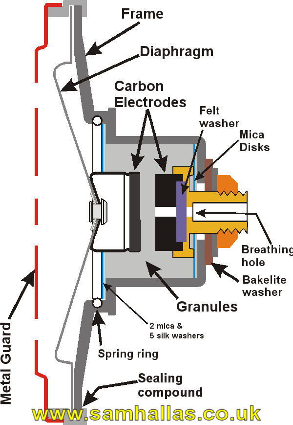
Fig 1. Transmitter Inset No 13, Sectional view
An inset transmitter consists of a carbon granule transmitter contained in a capsule which is connected by sprung contacts when it is placed in position in the telephone case. It means that a faulty transmitter can be easily replaced on site.
The solid back transmitter, described in part 5, was very suitable for the majority of Post Office telephones in the early 20th century since they were mainly wall or pillar types where the transmitter was always kept vertical. The change to a handset, or Microtelephone as the Post Office quaintly described it, needed a transmitter that worked comfortably at other orientations.
Early handsets had disappointing transmission characteristics and so in 1927 the Post Office Research Department was tasked to produce a new design. The remit involved improved transmission performance, working at all angles, and a reduced tendency for packing of the granules.
At the same time Siemens Brothers were working on a design of their own, patented in 1929, which equalled the performance of the Post Office one. Both designs were adopted in 1929 for a trial period as Transmitter Inset No 10.
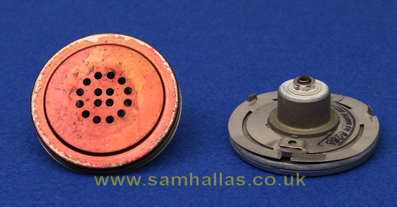
Fig 2. Transmitter Inset No 13 Front & back
Further improvements were made to the Siemens design in 1937 and it became Transmitter Inset No 13.
A light aluminium alloy diaphragm, enamelled to protect against moisture, is coupled to an aluminium cylinder with a carbon electrode attached. The cylinder projects into the granule chamber, sealed by mica washers. The fixed electrode is mounted on the end of a tube which forms the connecting socket and is insulated from the case. By keeping the electrodes permanently immersed in granules, the transmitter performs well at all angles.
The front is hermetically sealed. To prevent damage to the diaphragm by changes in air pressure, a breathing hole is provided in the back electrode.
Summary: Transmitter Inset No 13 had a long service life. It was used in the Bakelite handset, Telephone No 164, in all telephone models Teles 162, 200 series and 300 series - until 1959. It even survived with slight connection modifications into the 700 series telephones until it was superseded by the inset No 16.
Addendum: Andy Emmerson notes that collectors may come across a simplified (flatter) variant of the P.O. No. 10 in some Ericsson (Beeston) handsets of the 1930s supplied to non-GPO customers. This was probably cheaper to make and avoided the need to pay royalties for using the No. 10 design.
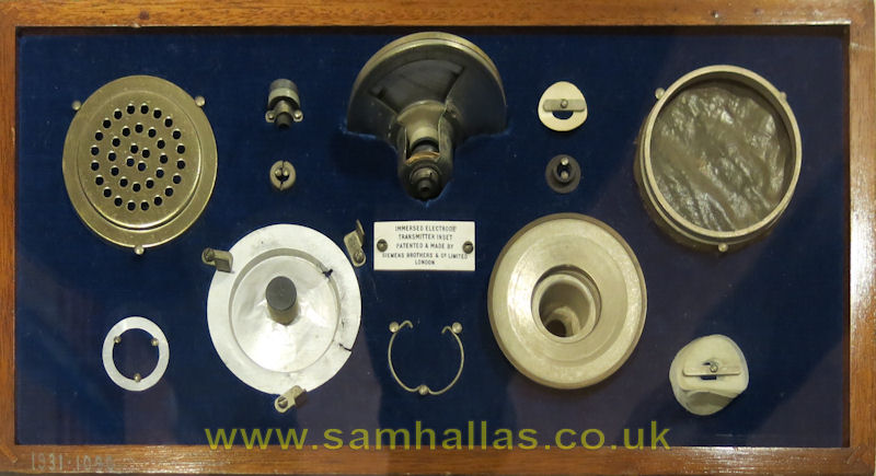
Fig 3. Inset No 10 parts, displayed in the Science Museum, London
Telephony, Atkinson, Pitman, 1949, Vol 1 Pp35 &36
Telephony, Herbert & Procter, Pitman, 1934, Vol 1 Pp237-239
UK Patent, 308630. Improvements in or relating to microphones.
Post Office Electrical Engineers Journal, Vol 22 (Oct 1929), p185. A new C.B. Microtelephone Aldridge, Barnes & Foulger.
POEEJ, Vol 29 ( Jan 1937), p335. Transmitter Inset No. 13 C.A.R. Pearce.
Fig 1 is redrawn, SMH, from diagram in Atkinson.
Fig 2 is © 2015 Sam Hallas
 The Hunnings