
Sam Hallas' Website
Although the Hunnings-Cone transmitter, described in the previous part, was an improvement on its predecessors, the Bell company continued development. Anthony White, a Bell employee patented this transmitter that became known as the Solid Back. [click the images for a larger view]

Fig 1. The Solid back transmitter in Section
Fig 1 shows the general arrangement. The capsule containing the carbon granules is bolted firmly to a metal frame hence the name solid back. The front of the capsule is attached to a light aluminium diaphragm, supported in a rubber ring, which receives the incoming sound.
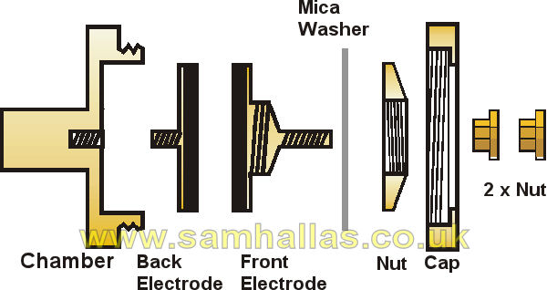
Fig 2: Exploded diagram of Capsule
The capsule is formed from a chamber lined with paper coated in shellac varnish for electrical insulation. The two electrodes are buttons of hard carbon with a high polish. Each is copper plated on one side and soldered to a brass disc. The back electrode has a stud which screws into the chamber housing. The front electrode is clamped by a nut to a thin mica washer which retains the carbon granules whilst allowing the electrode to move like a piston in the granule chamber.
A threaded stud projects from the front electrode allowing it to be fixed to the aluminium diaphragm. A threaded cap fits over the whole chamber to retain the electrode and granules in place. One or more flat, rubber-tipped springs press on the diaphragm to damp any persistent vibration.
The Solid Back was a most efficient transmitter for its day and began to replace the Blake transmitter from the 1890s onwards. It was used by the British Post Office on their telephones No 1 and No 2. It remained a standard BPO transmitter for central battery telephones until overtaken by the inset transmitter No 10 in the late 1920s.
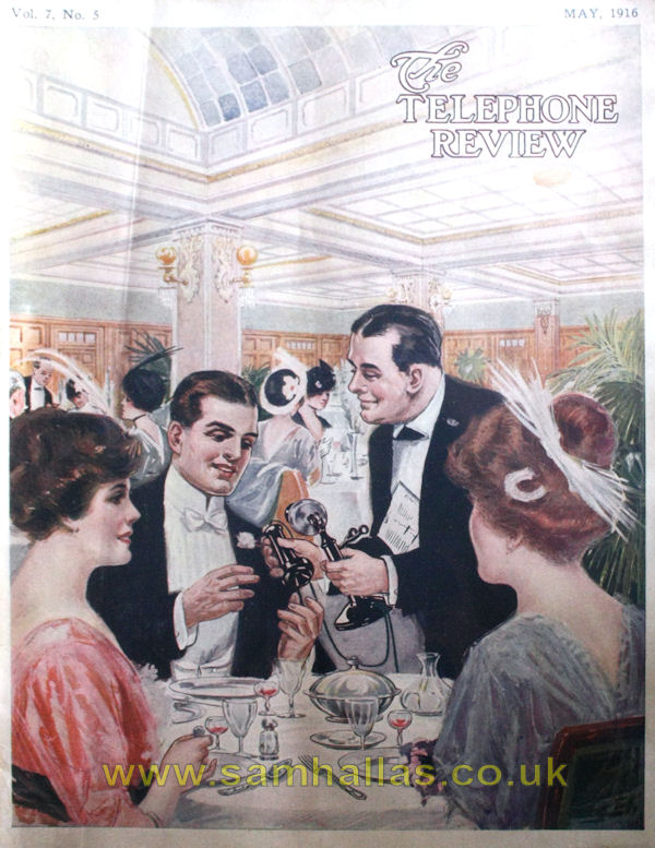
Fig 3. Telephone No 2 in use
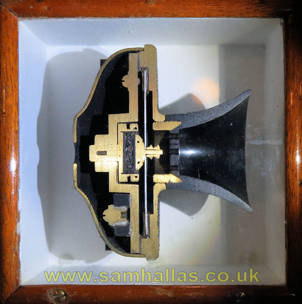
Solid back transmitter in section
on display in the Science Museum
Telephony, Part V, The substation, Arthur V. Abbott, McGraw Publishing, New York, 1904
U.S. Patent 485,311
Figs 1 & 2 is redrawn SMH from diagram in Abbot, Fig 2 from the US Patent.
Fig 3 is © 1916 The Telephone Review, Fig 4 Photo © 2013 SMH
This article was published in the Telecommunications Heritage Journal Issue 75, Spring 2012
 The Hunnings
Transmitter Inset Nos 10 & 13
The Hunnings
Transmitter Inset Nos 10 & 13