
Sam Hallas' Website
The Trimphone, Telephone Number 722, has become something of a design icon from the 1960s.
The Post Office commissioned the design to be "a luxury item of distinctive appearance, small, dainty and deluxe" [Ref 1]. The winning design came from STC and it featured a number of firsts: tone caller, unique handset, and illuminated dial. The name is supposedly derived from 'tone ringing, illuminated model' but the acronym might have been invented in retrospect as it is indeed a very trim looking telephone.
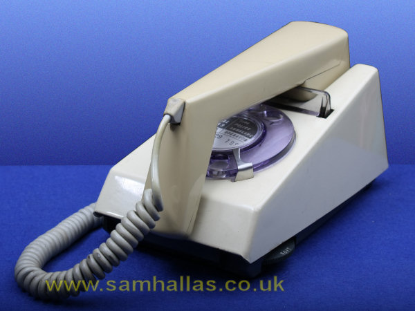
This is the telephone I'm going to take apart. I've actually only just reassembled it from a box of bits acquired at some THG meeting. The photograph flatters it somewhat as, like most old plastic items, it has faded badly over the years.
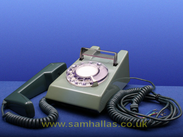
Here's an overall view of a trimphone so you can see that it came with an unusually long desk cord with a coiled section so that the phone could be carried around the room. As an aid to this the cradle rest doubles as a handle when the phone is off-hook.
The trimphone is surprisingly light and this was a source of trouble to the dial model since it tended to skid around during dialling. It was noticeable that when trimphones were displayed for sale, they were invariably placed on a rough surface with good friction such as felt.
The handset cord comes out at the side of the phone, just behind the dial. This makes sense for a front-to-back design like this, which was also an unusual feature. The desk cord, more conventionally, comes out of the back.
The cover and base are thermoplastic mouldings. The cover is ABS. The base on the original Telephone 712 was described as toughened polystyrene. I'm not sure if this choice of material has carried through to the 722. The cradle rest is moulded in what's described as 'smoke-tinted' polycarbonate. This is a plastic with a clear, bright appearance and high shatter resistance. It's also the plastic chosen for the dial finger plate.
The cover is held in place by a single nylon screw behind the cradle rest and two lugs at the front which mate with recesses in the base. It isn't clear why nylon was chosen for the screw material. It may be for its resilience to cushion vibration when the telephone is carried around by its cradle rest. Or maybe it's for insulation, so there is no exposed metal. It could also stop the handset being scratched if the screw was not fully home.
Loosen the screw - it is quite long, so it can be unscrewed enough to release the lid, but doesn't have to come right out just now. Lift the case from the back and tip forward to release the lugs. The insides are now accessible.
Let's have a look at the cradle rest and its mechanism before we take it apart.
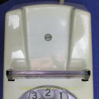
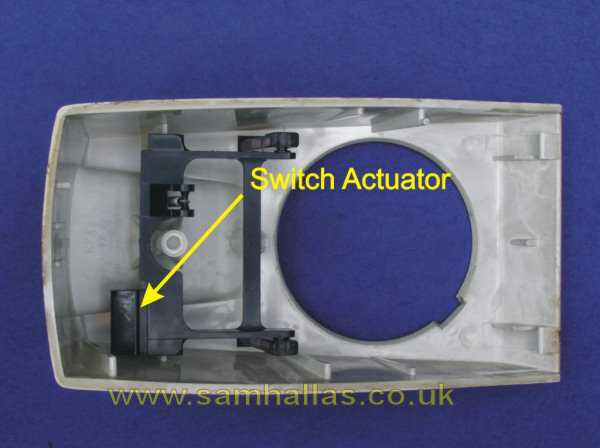
Turn the cover over and look for the switch actuator - see picture left. Press and release the cradle rest and you'll see that the actuator works in reverse. It's down when the cradle is up. This means that the telephone is on-hook when the lid is removed. The Telecomms Instruction [Ref 3] mentions this as a feature, since it obviates any need for a latch. I think it's a consequence of the light weight of the handset. This means there's a need for the mechanical advantage of the lever action in order to work the switch reliably. The inversion of the action is just a by-product of having a lever.
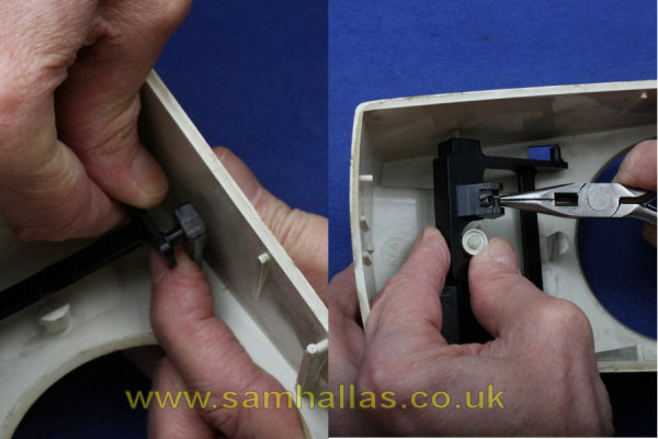
The cradle rest mechanism can be removed from the case allowing the parts to be cleaned separately. With the rest pressed against the case, squeeze each of its legs apart until they detach from the lever. Carefully unhook the spring from the lever using a pair of pliers and lift the lever off its knife edge - pictures right Now is also a good time to take the cover fixing screw fully out.
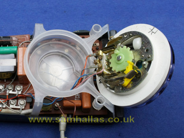
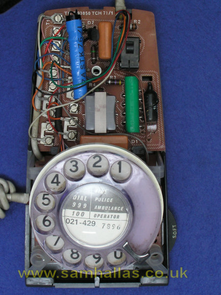
The dial mounting is quite cunning. The dial sits in a polythene moulding with hooked rear feet and is held in place by the pressure from the case. No screws are needed due to the springiness of the polythene. It's time to disconnect the dial now. Here's a picture of the connections (right) to save you working them out from the diagram when you come to reconnect it.
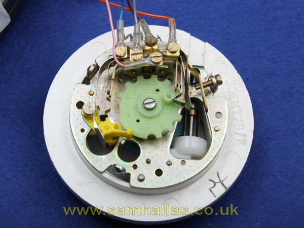
I'm not going to deal with servicing the dial, as that's a whole topic in itself. However the dial fitted to trimphones, Dial No 30, is unusual in being illuminated. So let's have a quick look. Take the window out with something suitably sticky. The correct tool is a rubber sucker, but I usually use Blu-tack™ or sticky tape. Remove the dial label and fixing screw and slide the finger plate off. Unclip the spring and lift the escutcheon off.
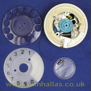
The luminous tube can now be seen running around the outside edge. By 2008 when I took these pictures, all traces of illumination had disappeared. Even in the pitch dark there was no glow at all. I presume that there's next to no radioactivity left. Wipe the parts clean and put the dial back together.
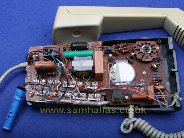
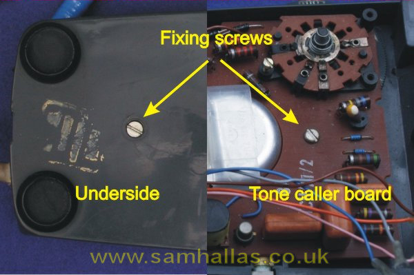
There are two circuit boards attached to the base: the transmission board on the left and the tone caller board on the right. The cords cannot be removed until the circuit boards have been taken off the base. Release the spade tags on the cords and then remove the two fixing screws holding the board in place. Notice that the one for the transmission board is on the underside. I've also disconnected the wires between the two boards. If you're only wanting to clean the case, don't bother.
The transmission circuit board uses the same circuit and terminal layout as the Telephone Number 706. However several components are smaller versions which had become available by the time the trimphone was being designed. The two capacitors are the smaller polyester types. The anti-sidetone transformer, Number 32, is much smaller than its predecessor, Number 31, used in the 706. The cradle switch is an enclosed microswitch. All these smaller components were to appear at about the same time in the Telephone Number 746. The other parts - the resistors and regulator are identical to the 706 ones.
The large blue object dangling at the back is the Regulator No 7. This is a shunt in parallel with the transmitter to prevent frying noise caused by too high a current on short lines. It is a later modification to the design, although this drawback of the transmitter No 15 was known earlier in the design process [Ref 1].
Notice that this circuit board has the track layout silk-screened onto the upper side. This is a feature that I like, a pity most of the other trimphones I've examined don't have it. The boards are single-sided and synthetic-resin bonded paper, SRBP, which is typical for the period. The underside of the board is coated except where there are solder pads. This is doubtless in preparation for automatic soldering, although all the joints on this board are hand soldered.
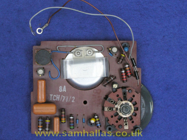
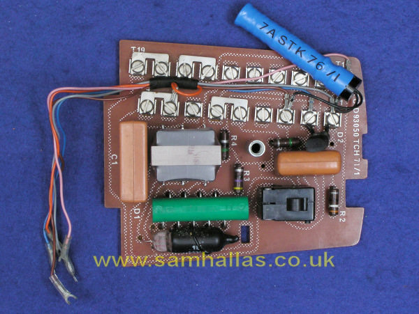
The tone caller, No 8A, was a novel feature of the trimphone. It consisted of an oscillator of about 2 kHz driven from rectified ringing current which gave it a vibrato effect. It is said that starlings learned to imitate the sound and many a person could be seen diving into the house on a summer afternoon thinking their trimphone was ringing.
The oscillator uses a tuned winding on a transformer (top left) and two transistors, which are BC108. Active devices in Post Office equipment are usually types with a Common Valve, CV, number, so it's unusual to find ordinary civilian parts here. The volume control (bottom right) has four settings: off, soft, loud and crescendo, where the level increases with time.
Earlier versions prior to the Telephone 2/722 were fitted with a slightly simpler design, tone caller No 5A, with only one transistor and which used a thermistor to provide the crescendo feature. The 8A uses a transistor fed by a capacitor with a bleed resistor. On each burst of ringing the capacitor charges up more than it discharges in the quiet period, until it is fully charged turning the transistor fully on to give maximum volume from the sounder. The sounder itself looks like a Receiver Inset 3T, as used in the Headset No 1. However, the markings on the back say 1/2B which suggests it is a special version modified to be most efficient at 2 kHz.
When the trimphone is the sole telephone in an installation the off position is disabled by placing the screw in the pillar at the lower left of the volume control. See Page 3 of the N-diagram, N822.
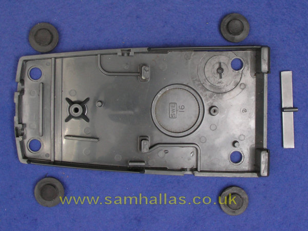
The base incorporates a section at the front which slides out. This is to accommodate a recall switch - see the next page.
The feet are the same type fitted to Telephone No 706. They can be removed by pulling from below whilst pushing the edge with a thumb nail from above. I found that the feet are much harder to put back than they are to get out. Press the rim against the base from below and force the rim though the hole using the blade of a small screwdriver. I should only take the feet out if you really need to.
The trimphone is now fully dismantled ready for cleaning or repair - apart from the handset, which I'll leave until last. Next let's look at the push-button versions.

Exhibits: Sam Hallas Collection
Photos & text: © Sam Hallas 2008