
Sam Hallas' Website
The design of the hookswitch mechanism has some good and bad points.
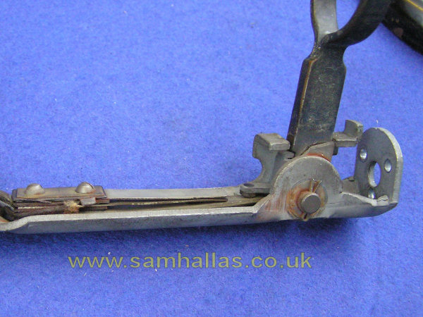
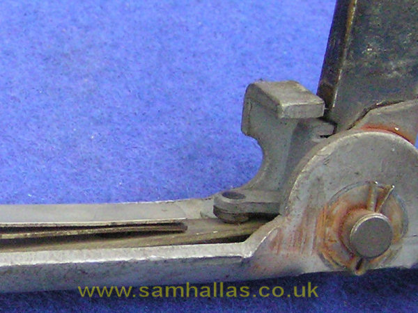
First the good points. Theres no need for a separate spring to raise the cradle when the receiver is lifted. The lower contact of the springset doubles as part of the double-make contact and lifting spring. See the close-up in the centre. The receiver cradle is easily detachable. Depress the steel rocker with the bakelite peg fully and pull the cradle out. You can take the whole pivot assembly out by removing the cotter pin, but unless its badly seized, there isnt any point. A drop of light oil is all thats needed to keep it working sweetly.
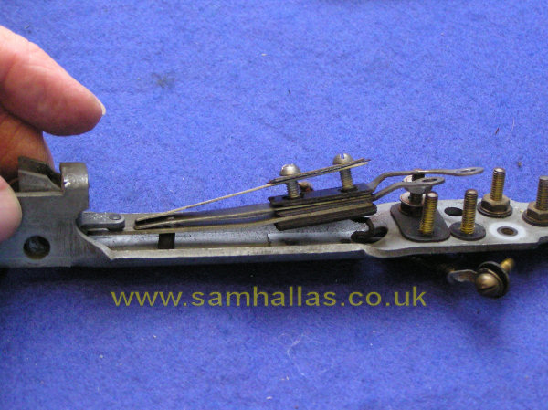
Now the bad points. The contact set is very difficult to remove see the right-hand picture. The method of connection by extending the contacts back to the terminal screws makes it very awkward. Its not self-contained: the contact spacing relies on a peg fitted in the chassis. The fixing screws also hold the contact assembly together. As you can see in the picture they tend to fall apart once the screws are removed.
The internal chassis in the telephone is evidently inherited from its predecessor, the Telephone No 2. It was a good idea when that telephone was designed, before automatic working added the complication of a dial. By the time of the Telephone 150, placing all the terminals in the confined space inside the shaft was less than ideal. It is a well-known fact that the most common faults on telephones related to the cords. So making the terminals more accessible would have been a good idea, but would have involved a total redesign of the chassis. It was probably not considered worth while in the aftermath of the Great War and with other developments in telephones looming.
Improvements in design of contact assemblies seems to be a lesson learned. Later designs, such as dial springs and relay contacts, used separate fixing screws from the screw holding them together.
The candlestick Telephone No 150 lived a somewhat charmed life. By the time it appeared GEC, Siemens and Ericsson were already developing self-contained bakelite telephones with handsets. This culminated in the adoption by the Post Office in 1929 of the Telephone 162. Nonetheless the 150 remained in service for a surprising length of time. The Post Offices policy of interchangeability of parts means that this 1928 vintage telephone is still in full working order, despite having a new dial, transmitter insert and cords.
First I must thank the retired British Telecom engineer, Ken Moss, who kindly donated this telephone to my collection.
Other acknowledgements are due to Peter Walker and Bob Freshwater, Ian Jolly and Ron Sewell for historical and technical information. Finally to Laurence Rudolph for scanning his diagram N250, of which I append one sheet as a reference to this article.
 Previous
Project Index
Previous
Project Index 