
Sam Hallas' Website
As I remarked earlier nearly everything about the Telephone No 706 was new. We saw the new handset cordage in the article on the Handset No 3 (previous page). The desk cord and block terminal were also new designs.
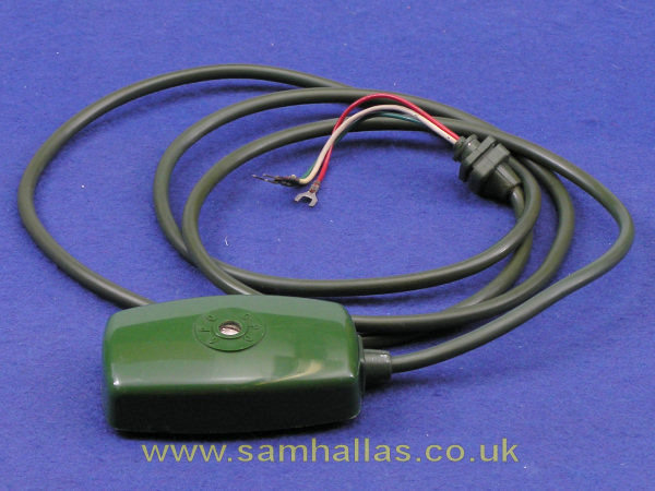
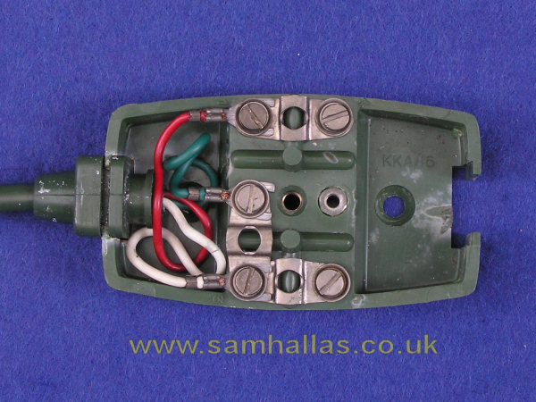
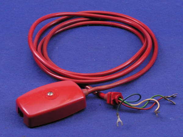
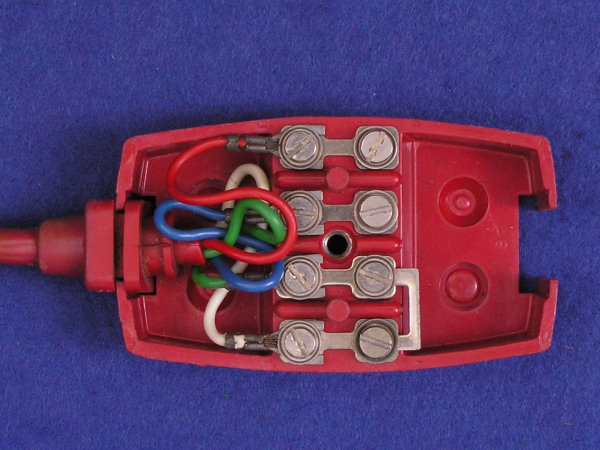
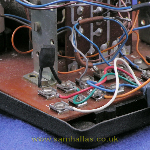
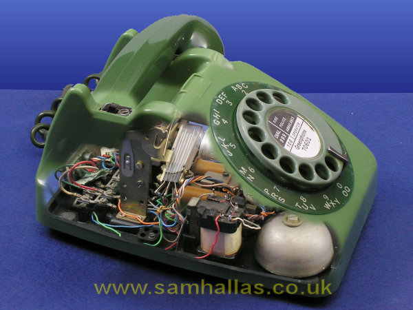
The initial cords were three-way to allow an extension bell but no more. For extension plan working a four-way cord was needed and this became standard later. The green telephone has a three-way cord and Block Terminal No 30. The red telephone has a four-way cord (Cord Instrument 4/88) and the, by now, more common Block Terminal No 52A.
As on the handset the new cordage does away with the need for tie strings by using a moulded grommet glued to the cable sheath. The wrapped wire loops are replaced by the simpler and cheaper spade tags. Replacing a damaged cord is much quicker with the new type.
It is my opinion that the Post Office exercised tight quality control over the quality of the plastics used in the cords and grommets. The ones I have are all between 25 and 45 years old, yet none have gone slimy and sticky. Some non-PO ones in my collection have deteriorated like that.
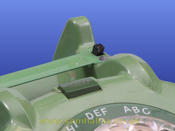
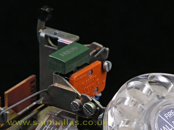
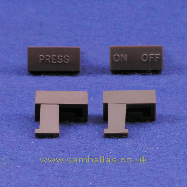
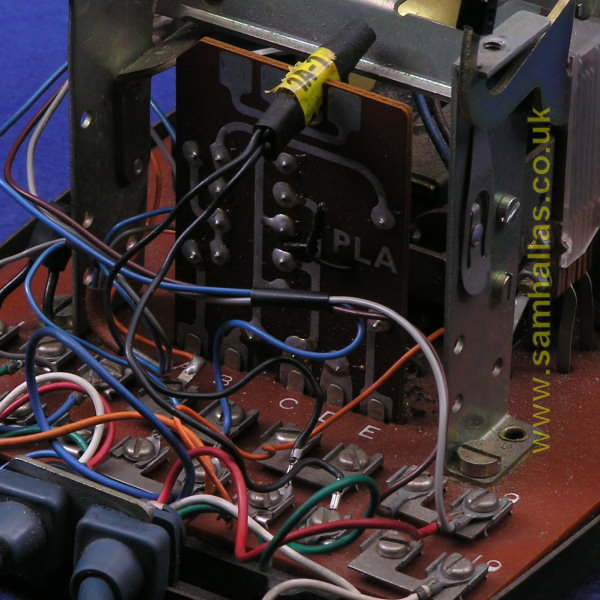
Unfortunately neither the green nor the red phone have been fitted with a press switch so we'll have to look elsewhere. On the left is a different green Tele 706 with a recall button marked 'Press'. On the right is how it mounts into the ready made groove and hole in the dial bracket inside as seen in this picture from earlier.
The button here is labelled 'Press' suitable for recall or call exchange on a shared service line. A different option button labelled 'On/ Off' can be used for a bell off function. It works by having an additional foot to its rear arm as seen which causes the button to tilt sideways when pressed so that it locks in the operated position. Pressing again on the higher side causes it to spring back up. Simple and clever.
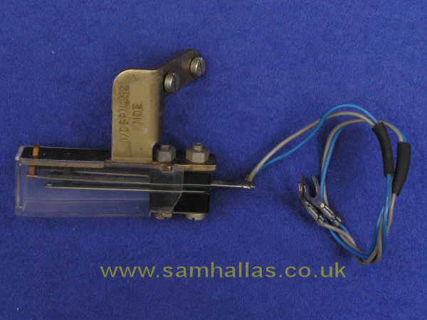
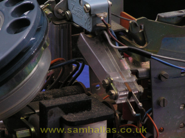
There are applications that require more contacts to be operated when the phone is off-hook than are provided in the basic circuit. A typical case is on extensions connected to a Switchboard PMBX 2/.. Here is a springset 1/DSP/1252 which has a single make contact. On the right is one in situ in a phone that was a PMBX extension. It fits on the right hand support pillar and operates in the same way as the main springset on the left hand pillar.
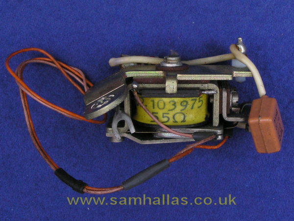
Buzzer No 32A is a small DC buzzer used, typically, on extensions on a Plan 105 or 107 to allow the main to buzz the extension on an intercom call or to transfer the exchange line. It mounts using one of the bell screws as seen on the right.
It looks like a tight fit, but there is room to get the case back on again - just.
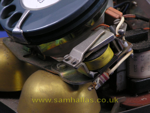
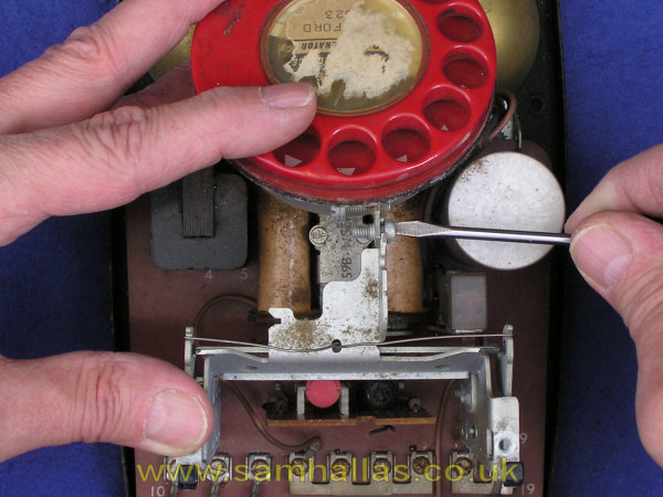
Rectifier element No 205A (left) consists of two diodes connected back-to-back - that is with the anode of one connected to the cathode of the other. It's purpose is to limit voltage surges to the receiver in order to protect the user against acoustic shock which could damage their hearing. It is fitted directly to terminals 1 and 2 as seen. Initially it was provided as an accessory but later it was fitted as standard as a routine safety measure. The style of construction varied by manufacturer. Some were in hard cases with moulded in spade terminals.
Thermistor No 1A-1 (right) was generally used on shared service lines (party lines) to prevent bell tinkle when the other party was using the phone. It was wired in series with the bell, replacing the strap between terminals 16 and 17. The thermistor has a high initial resistance preventing the bell from ringing. After a short burst of ringing current it warms up so that its resistance reduces sufficiently to allow the bell to ring. It always seemed to be the practice to push the thermistor into the U-shaped cutout in the regulator to hold it firm.
Notice that the phone on the right is the one with the additional springset and so it has an extra wire in the desk cord, coloured orange. I only fitted the thermistor to photograph it. It was not there originally.
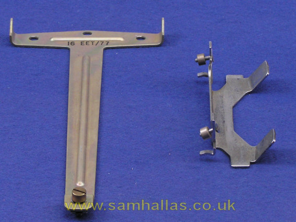
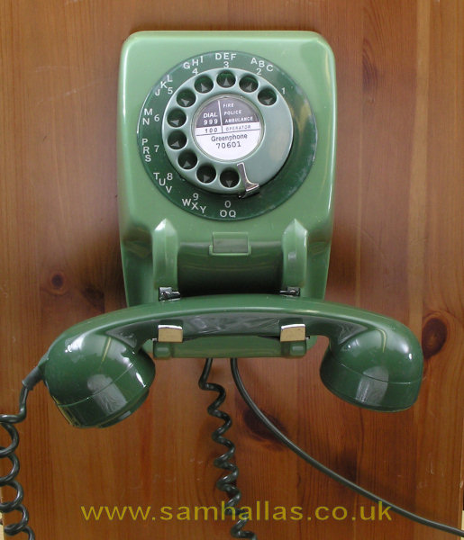
The wall telephone in the 700-series, Telephone No 711, was not available immediately. As some sort of stopgap this adaptation, right, was issued as Telephone 1/706, a rebadged version of Ericsson's N1065. Some private suppliers used the kit shown on the left to make wall telephones available without increasing their inventory by stocking the Tele 711 separately.
The T-shaped bracket is fixed to the wall. The Telephone No 706 has its dial and outer number ring reversed and its feet removed. The case fixing escutcheons are removed and replaced with the chromed bracket. The telephone can then be hung from the top of the T-bracket and fixed with the screw at the bottom.
Several other accessories are listed in Reference 1. Unfortunately I don't have samples to photograph. However, the list is proof of the versatility of the 706 design.
Telephone No 706 was as much a design revolution compared with its predecessor, Tele No 332, as Telephone 162 was with its predecessor, Tele No 150. The older generation Bakelite telephone had been the Post Office standard for over 25 years. Obviously development was hampered by the Second World War, but the Post Office might be accused of dragging its feet in adopting the various innovations in circuit and mechanical design by the likes of GEC and Ericsson. Nonetheless Telephone 706 was worth waiting for.
The smooth lines of the case and handset were right for the modern era of the Fifties. The transmission was improved ready for the future explosion of subscriber trunk dialling which started the previous year.
The 706 electrical circuit design made it the most versatile telephone yet developed in terms of the number of different ways the basic circuit could be configured - central battery, local battery, shared service, extension plan working and so on. The most frequently used variants - press to call/ recall and bell on/ off were included in the basic design.
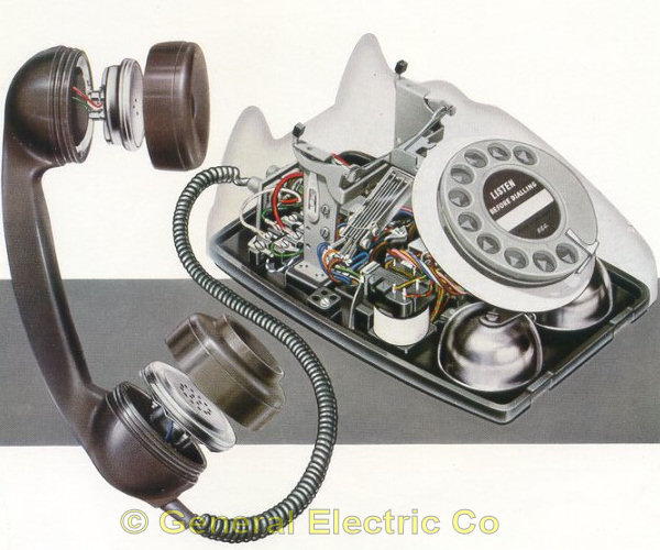
Left is a picture from a GEC sales brochure advertising their version of the Telephone 706. [Bob Freshwater collection] Right is my modern recreation of a cutaway picture.
However the days of the 706's supremacy were numbered. The younger and cheaper upstart, Telephone No 746 came on the market only a few years later.
Anyway, happy 50th birthday, Telephone No 706!
Many thanks to the people who sent advice and corrections: Paul Ebling, Geoff Mawdsely, Jack Ryan, Adrian Rodsett, Peter Walker.
 Handset No 3
Project Index
Handset No 3
Project Index