
Sam Hallas' Website
I have frequently wondered when looking at early telephones in books or in museums what the difference was between the various carbon transmitters named - Blake, Hunnings, Solid Back, etc. As an exercise in self-education I've compiled a series of one-page articles about transmitters, sticking to mainstream designs (used in the UK) as much as possible. This is intended to be a distillation of information already available, but scattered about, and with the diagrams redrawn for improved clarity.[click the images for a larger view]
Soon after Bell introduced his telephone it became evident that the use of the same device as both receiver and transmitter was a factor limiting its range. The electrical power of the outgoing speech was entirely dependent on the power in the human voice activating the transmitter. The latter half of the nineteenth century was a time of feverish invention. So the search was on to find improvements to telephone transmitters.
Thomas Edison
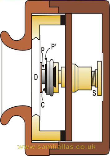
Edison Transmitter sectional view
Thomas Edison, (1847-1931) discovered independently that carbon was the best material for a transmitter. Edison's patent, US Pat No 474,230, was filed in 1877, but not granted until 1892 following a long-running legal wrangle. The patent described a complete telephone system which Edison called quaintly a 'speaking telegraph'. The patent refers to the transmitter having an electrode of hard rubber coated with plumbago (ie graphite). The receiver used an electromagnet to move a diaphragm.
Development must have continued because by 1891 William Preece (1834-1913), Chief Engineer to the British Post Office in the ninth edition of his Telegraphy shows Edison's transmitter using a carbon button between platinum electrodes. The following is a paraphrase of Preece's description.
An ebonite case contains a vibrating disc D , and a button of carbon, C, fixed between two discs of platinum, P and P' which act as electrodes. The platinum electrode P is attached to the disc D by means of a cork pad, and the pressure between P' and the carbon button C can be regulated by the screw S. When the disc D is spoken against it vibrates, and its vibrations tend to lessen or increase the pressure upon the carbon button C. As the pressure varies, so does the resistance at the point of contact of the carbon button and the platinum. By passing a current through the carbon its strength will vary with the resistance, and consequently the incident sound.
The use of a battery to drive the transmitter increased the power that could be passed to the telephone line. Similarly, an induction coil stepped the output voltage up to match the sensitivity of a telephone receiver.
Development continued on improving the carbon microphone. The following year, 1878, David Hughes published his paper on the microphonic properties of carbon. This led to further designs which will be described in the next part.
Telegraphy, 9th Edition, W.H. Preece & J. Sivewright, Longmans, Green & Co, London, 1891 (available at http://openlibrary.org/)
US Patent No 474,230
Carbon Microphone: Wikipedia
Sectional view redrawn from Preece & Sivewright.
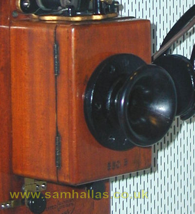
Exhibit photo: Science Museum, London © 1999 Sam Hallas
This article was published in the Telecommunications Heritage Journal Issue 74, Spring 2011
